Difference between revisions of "3 Bottom IO port control"
| (2 intermediate revisions by the same user not shown) | |||
| Line 1: | Line 1: | ||
| − | + | [[File:Webduino_gif.gif|thumb|Overview: [[BPI-Bit]]]] | |
[[File:Micropython3.png|thumb|[[1 Get the development suite]] ]] | [[File:Micropython3.png|thumb|[[1 Get the development suite]] ]] | ||
[[File:Micropython2.png|thumb|[[2 Wired connection board]] ]] | [[File:Micropython2.png|thumb|[[2 Wired connection board]] ]] | ||
| Line 11: | Line 11: | ||
[[File:Micropython2.png|thumb|[[3 Mpfshell details]] ]] | [[File:Micropython2.png|thumb|[[3 Mpfshell details]] ]] | ||
[[File:Micropython2.png|thumb|[[4 Pycharm IDE programming]] ]] | [[File:Micropython2.png|thumb|[[4 Pycharm IDE programming]] ]] | ||
| − | + | ||
| − | |||
[[File:Micropython5.png|thumb|[[1. Panel scrolling text]] ]] | [[File:Micropython5.png|thumb|[[1. Panel scrolling text]] ]] | ||
| Line 27: | Line 26: | ||
[[File:Micropython2.png|thumb|[[12 S2m Scratch2]] ]] | [[File:Micropython2.png|thumb|[[12 S2m Scratch2]] ]] | ||
[[File:Micropython2.png|thumb|[[13 Codelab Scratch3]] ]] | [[File:Micropython2.png|thumb|[[13 Codelab Scratch3]] ]] | ||
| + | |||
| + | [[File:Micropython6.png|thumb|[[1 The basic algorithm]] ]] | ||
| + | [[File:Micropython2.png|thumb|[[2 WiFI wireless connection]] ]] | ||
| + | [[File:Micropython2.png|thumb|[[3 WiFI wireless programming]] ]] | ||
| + | [[File:Micropython2.png|thumb|[[MQTT communication applications]]]] | ||
How to control the board's input and output! | How to control the board's input and output! | ||
Latest revision as of 02:38, 21 February 2019
How to control the board's input and output!
IO in the computer refers to Input/Output, namely Input and Output, referred to as IO port.
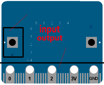
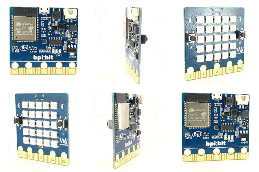
- IO ports are different, some are larger, and in general, there are tags near them for users to understand. For example, the bottom of this board is distributed on goldfinger in the order of 0/1/2/3V/GND (most computers start from 0).
- If you attach the gold finger to the base, other smaller blue and white line pins can be used as well, which was specifically noted in the introduction of the hardware in chapter 1. You can forget to check the BPI:bit hardware.
- In this module of microbit, the interface of the board is defined as pinN object, where N represents the value of the interface, so the no. 0 interface is also called pin0 object. If you find this is not easy to use later, you can redefine your favorite Pin name by import machine Pin.
Shy board
We want to touch the pin of the board and make it respond accordingly, and it looks like a shy little girl.
code as below:
from microbit import *
while True:
   if pin1.is_touched():
       display.show(Image.HAPPY)
   else:
       display.show(Image.SAD)
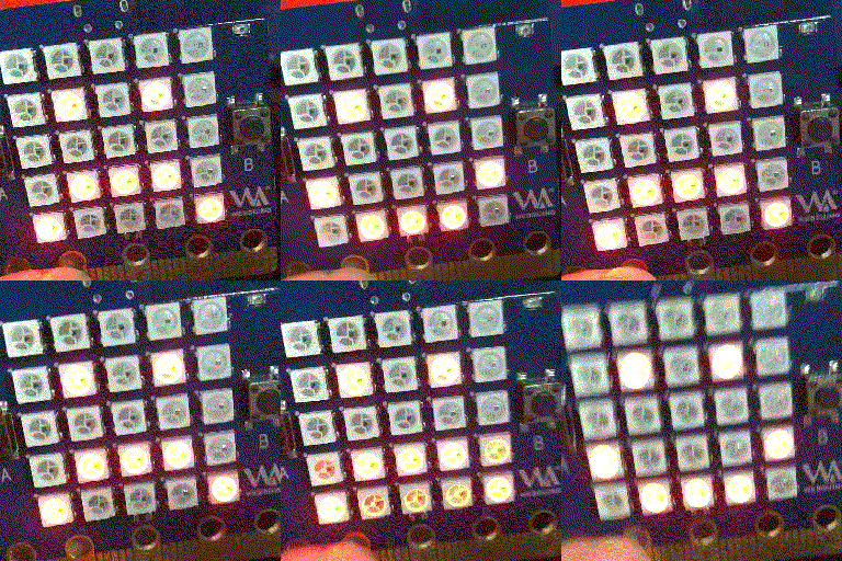
At this time, you need a hand to touch the pin of tag 1, you can see the board from sad to happy, if you release it, it will change the expression, is angry?
The procedure is explained as follows:
- On "pin1. Is_touched ()" repeatedly run to determine whether or not the pin is touched. (principle is ADC sampling)
- It runs and returns True, which shows a smiley face, otherwise it always shows a bitter face, so it will feel sad when you don't touch it. (and so on! What kind of shyness is this!!!! )
The running effect is as follows:
It should be noted that since we have static electricity in our body (hands), it may be electrocuted and cause its expression to twitch sometimes.
lamp ON or OFF
When we first started, we had already learned how to control the changes of LED lights on the board, but it was all done by others. So today we will have a try. How did others do it?
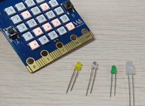
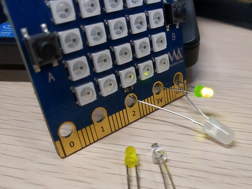
For this purpose, I have prepared the following common Led lights, and you will find that they are of different lengths. This is to distinguish their positive and negative poles. The positive pole is the long end, so the negative pole is the short end.
Tip: the purpose of distinguishing the positive and negative poles is to hope that when you are wiring, the element (LED) positive pole is connected to the power positive pole (+), and the element (LED) negative pole is connected to the power negative pole
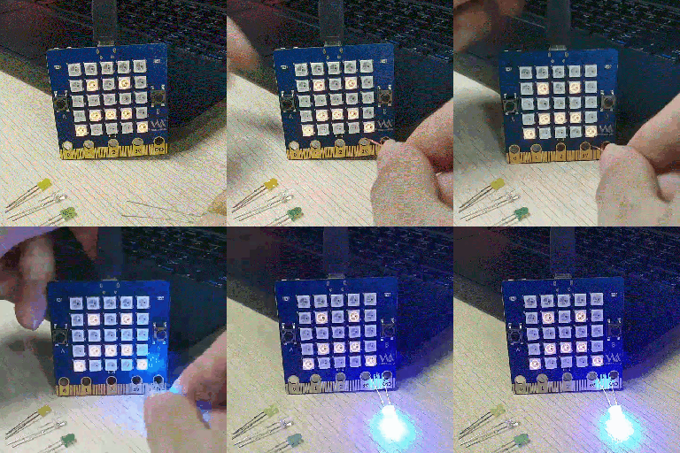
Let's start with the first step, which is to turn on the ordinary light, that is, directly connect it (LED) to the power supply, then directly connect the big guy to the board of 3V and GND, 3V refers to the positive pole of the power supply (3V), GND refers to the negative level of the power supply, also known as the ground.
This lights up a light (pay attention to the positive and negative), but the light is not controllable, it will only light up, not out.
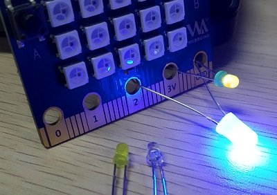
I wanted to take another lamp to connect it for comparison, but I found a problem that the other lights were too short, so I changed the following. I used our headlight to control, and it can be seen that the lamp will not be on at this time.
So let's control its on and off by the following code, you can see in the picture I used pin2 pin to control.
from microbit import *
pin2.write_digital(1)
Now I use the Pycharm + Mpfshell plug-in to run this code.
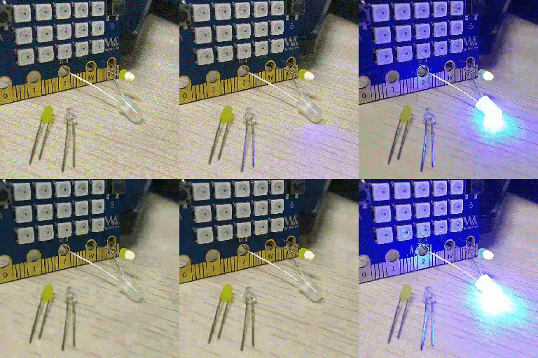
You can see it lights up, so that means we can control the light, is that consistent with the initial tutorial?
So let's add a Blink effect this time, using the following code.
from microbit import *
while True:
   pin2.write_digital(1)
   sleep(200)
   pin2.write_digital(0)
   sleep(1000)
Let me explain the procedure:
- Use pin2 pin to output 1, which will make the LED become high level. Simply think that this pin has voltage, the effect is equivalent to directly connected to the positive pole of the power supply.(the potential difference between the two pins should be understood in principle)
- Light it up first, namely pin2.write_digital(1), and then use sleep(200) to rest the board for 200 milliseconds.
- Then you put it out, which is pin2.write_digital(0), and rest for another 1,000 milliseconds, or one second.
- Do it all over again.
