Difference between revisions of "Banana Pi BPI-W3"
(→Documents) |
(→Getting Start) |
||
| (70 intermediate revisions by one other user not shown) | |||
| Line 3: | Line 3: | ||
=Introduction= | =Introduction= | ||
[[File:Banana Pi BPI-W3 LGA 1.jpg|thumb|[[Banana Pi BPI-W3]] with Rockchip RK3588 chip design]] | [[File:Banana Pi BPI-W3 LGA 1.jpg|thumb|[[Banana Pi BPI-W3]] with Rockchip RK3588 chip design]] | ||
| + | [[File:Banana_Pi_BPI-M7_1.jpg|thumb|[[Banana Pi BPI-M7]] with Rockchip RK3588 chip design]] | ||
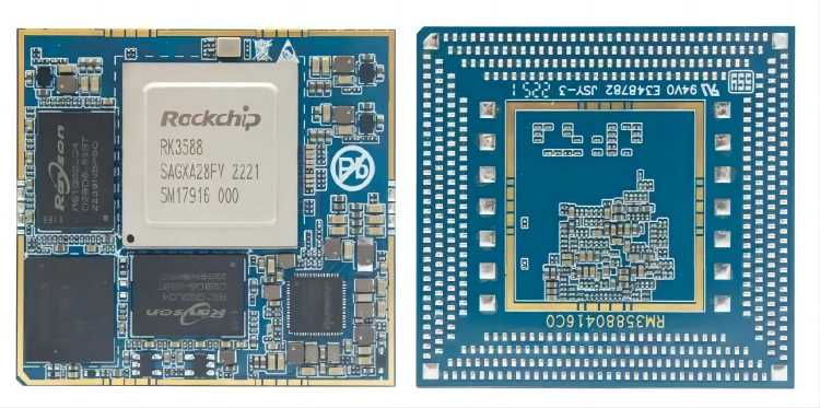
[[File:Banana_Pi_BPI-RK3588-LGA_5.jpg|thumb| RK3588 LGA BGA core board with Rockchip RK3588]] | [[File:Banana_Pi_BPI-RK3588-LGA_5.jpg|thumb| RK3588 LGA BGA core board with Rockchip RK3588]] | ||
[[File:BPI-RK3588_board_core_2.jpg|thumb|[[BPI-RK3588 Core board and development Kit]] Gold finger interface core board]] | [[File:BPI-RK3588_board_core_2.jpg|thumb|[[BPI-RK3588 Core board and development Kit]] Gold finger interface core board]] | ||
| Line 27: | Line 28: | ||
==Getting Start== | ==Getting Start== | ||
| − | [[Getting Started with BPI-W3]] | + | *[[Getting Started with BPI-W3]] |
=Hardware= | =Hardware= | ||
| Line 33: | Line 34: | ||
[[File:Banana_Pi_BPI-W3_interface_800.jpg]] | [[File:Banana_Pi_BPI-W3_interface_800.jpg]] | ||
| − | ==LGA Core board== | + | ==BPI-3588-LGA Core board== |
Banana Pi BPI-W3 base on [[BPI-RK3588 Core board and development Kit]] use BPI-RK3588-LGA core board. so you can easy to do new design with BPI-W3, just need to development a new base board. | Banana Pi BPI-W3 base on [[BPI-RK3588 Core board and development Kit]] use BPI-RK3588-LGA core board. so you can easy to do new design with BPI-W3, just need to development a new base board. | ||
| + | |||
| + | BPI-3588-LGA core board uses the Rockchip RK3588 flagship chip,integrating a 6Tops NPU and a high-performance quad-core Mali-G610 MP4 GPU. It adopts LGA 506pin package method, which can expand a variety of display interfaces and industrial application interfaces. With open baseboard design materials and open-source SDKs, it can be efficiently developed. It supports multiple operating systems such as Android, Ubuntu, Debian, and Buildroot. It provides robust, stable, reliable, and expandable product support for various AI application scenarios, and is widely applicable to fields such as edge computing, artificial intelligence,cloud computing, VR/AR, blockchain, smart security, intelligent industrial control, and smart home. | ||
[[File:Banana_Pi_BPI-RK3588-LGA_1.jpg]] | [[File:Banana_Pi_BPI-RK3588-LGA_1.jpg]] | ||
| − | ==Hardware spec== | + | ===BPI-3588-LGA spec=== |
| + | |||
| + | {| class="wikitable" | ||
| + | | | ||
| + | |SOC | ||
| + | |Rockchip RK3588 | ||
| + | |- | ||
| + | |CPU | ||
| + | |Quad Core [email protected] +Quad Core [email protected], 8nm | ||
| + | |- | ||
| + | |GPU | ||
| + | |ARM Mali-G610 MP4 GPU,Support OpenGL ES3.2 / OpenCL 2.2 / Vulkan1.1 | ||
| + | |- | ||
| + | |NPU | ||
| + | |6 TOPS@INT8,Support INT4/INT8/INT16 mixed operation Support framework switching of TensorFlow/MXNet/PyTorch/Caffe | ||
| + | |- | ||
| + | |ISP | ||
| + | |48-Megapixel ISP,It implements a lot of algorithm accelerators, such as HDR, 3A, LSC, 3DNR, 2DNR, sharpening, dehaze, fisheye correction, gamma correction and so on. | ||
| + | |- | ||
| + | |Encode&Decode | ||
| + | |Decode:8K@60fps H.265/VP9/AVS2,8K@30fps H.264 AVC/MVC, 4K@60fps AV1, 1080P@60fps MPEG-2/-1/VC-1/VP8 | ||
| + | Encode:8K@30fps H.265 / H.264 | ||
| + | |- | ||
| + | |RAM | ||
| + | |4GB/8GB/16GB(up to 32GB)64-bit LPDDR4/LPDDR4x, Defalut LPDDR4x 8GB | ||
| + | |- | ||
| + | |Flash | ||
| + | |16GB/32GB/64GB/128GB/256GB eMMC, support MicroSD card slot, Defaut eMMC 32GB | ||
| + | |- | ||
| + | |Operating Systems | ||
| + | |Android 12.0, Ubuntu 20.04, Ubuntu 22.04, Debian11, Buildroot, Armbian, Kylin OS | ||
| + | |- | ||
| + | |Power supply || 4.0V | ||
| + | |- | ||
| + | |Interface Type | ||
| + | |LGA 506pin | ||
| + | |- | ||
| + | |Size | ||
| + | |45mm×50mm×4.5mm(top: 2.2mm+PCB: 1.2mm +bottom: 1.1mm) | ||
| + | |- | ||
| + | |Operating temperature | ||
| + | | 0℃ ~ 70℃ | ||
| + | |- | ||
| + | |Storage temperature | ||
| + | | -20℃ ~ 70℃ | ||
| + | |} | ||
| + | |||
| + | === Function parameter === | ||
| + | |||
| + | {| class="wikitable" | ||
| + | |- | ||
| + | !Category !! Function !! quantity !! colspan="2" | parameter | ||
| + | |- | ||
| + | |rowspan="4" | Video Input Interface || MIPI DC(DPHY/CPHY) combo PHY || 2 || | ||
| + | * Support to use DPHY or CPHY | ||
| + | * Each MIPI DPHY V2.0, 4lanes, 4.5Gbps per lane | ||
| + | * Each MIPI CPHY V1.1, 3lanes, 2.5Gsps per lane | ||
| + | |||
| + | | rowspan="2" | Support camera input combination: | ||
| + | * 2 MIPI DCPHY + 4 MIPI CSI DPHY(2 lanes) | ||
| + | * 2 MIPI DCPHY + 1 MIPI CSI DPHY(4 lanes) + 2 MIPI CSI DPHY(2 lanes) | ||
| + | * 2 MIPI DCPHY + 2 MIPI CSI DPHY(4 lanes) | ||
| + | |||
| + | |- | ||
| + | |MIPI CSI DPHY || 4 || | ||
| + | * Each MIPI DPHY V1.2, 2lanes, 2.5Gbps per lane | ||
| + | * Support to combine 2 DPHY together to one 4lanes | ||
| + | |||
| + | |- | ||
| + | |DVP || ≤1|| colspan="2" | | ||
| + | * One 8/10/12/16-bit standard DVP interface, up to 150MHz input data | ||
| + | * Support BT.601/BT.656 and BT.1120 VI interface | ||
| + | * Support the polarity of pixel_clk, hsync, vsync configurable | ||
| + | |||
| + | |- | ||
| + | |HDMI RX || 1|| colspan="2" | | ||
| + | * HDMI 2.0 RX PHY, 4 lanes, no sideband channels | ||
| + | * Data rate support in HDMI 2.0 mode, 6Gbps down to 3.4Gbps | ||
| + | * Data rate support in HDMI 1.4 mode, 3.4Gbps down to 250Mbps | ||
| + | * Support HDCP2.3 and HDCP1.4 | ||
| + | |||
| + | |- | ||
| + | |rowspan="4" | Display interface || HDMI/eDP TX interface || ≤2 || colspan="2" | | ||
| + | * Support two HDMI/eDP TX combo interface, but HDMI and eDP can not work at the same time for each interface | ||
| + | * Support x1, x2 and x4 configuration for each interface | ||
| + | * Support up to 7680x4320@60Hz for HDMI TX, and 4K@60Hz for eDP | ||
| + | * Support HDCP2.3 for HDMI TX, and HDCP1.3 for eDP | ||
| + | |||
| + | |- | ||
| + | |DP TX || 2 || colspan="2" | | ||
| + | * Support 2 DP TX 1.4a interface which combo with USB3.1 Gen1 | ||
| + | * Support up to 7680x4320@30Hz | ||
| + | * Support Single Stream Transport(SST) | ||
| + | * Support HDCP2.3, HDCP 1.3 | ||
| + | |- | ||
| + | |MIPI DSI || 2 || colspan="2" | | ||
| + | * Support 2 MIPI DPHY 2.0 or CPHY 1.1 interface | ||
| + | * Support 4 data lanes and 4.5Gbps maximum data rate per lane for DPHY | ||
| + | * Support 3 data trios and 2.0Gsps maximum data rate per trio for CPHY | ||
| + | * Support dual MIPI display: left-right mode, RGB(up to 10bit) format | ||
| + | |- | ||
| + | |BT.1120 video output || ≤1 || colspan="2" | | ||
| + | * Support up to 1920x1080@60Hz, RGB(up to 8bit) format | ||
| + | * Up to 150MHz data rate | ||
| + | |||
| + | |- | ||
| + | |rowspan="3" | Audio Interface || I2S || ≤4 || colspan="2" | | ||
| + | * I2S0/I2S1, 8 channels TX and 8 channels RX path, audio resolution from 16bits to 32bits, Sample rate up to 192KHz | ||
| + | * I2S2/I2S3, 2 channels TX and 2 channels RX path, audio resolution from 16bits to 32bits, Sample rate up to 192KHz | ||
| + | * Support up to 7680x4320@60Hz for HDMI TX, and 4K@60Hz for eDP | ||
| + | * Support HDCP2.3 for HDMI TX, and HDCP1.3 for eDP | ||
| + | |||
| + | |- | ||
| + | |SPDIF || ≤2 || colspan="2" | | ||
| + | * Support two 16-bit audio data store together in one 32-bit wide location | ||
| + | * Support biphase format stereo audio data output | ||
| + | |||
| + | |- | ||
| + | |PDM || ≤2 || colspan="2" | | ||
| + | * Up to 8 channels, Audio resolution from 16bits to 24bits, Sample rate up to 192KHz | ||
| + | * Support PDM master receive mode | ||
| + | |||
| + | |- | ||
| + | | Network interface || GMAC || ≤2 || colspan="2" | | ||
| + | * Support 10/100/1000-Mbps data transfer rates with the RGMII interfaces | ||
| + | * Support both full-duplex and half-duplex operation | ||
| + | |||
| + | |- | ||
| + | |rowspan="10" | Connectivity interface || SDIO || ≤1 || colspan="2" | | ||
| + | * Compatible with SDIO3.0 protocol | ||
| + | * 4-bit data bus widths | ||
| + | |||
| + | |- | ||
| + | |USB 2.0 Host || 2 || colspan="2" | | ||
| + | * Compatible with USB 2.0 specification | ||
| + | * Supports high-speed(480Mbps), full-speed(12Mbps) and low-speed(1.5Mbps) mode | ||
| + | |||
| + | |- | ||
| + | |SATA || ≤3 || | ||
| + | * Support three SATA3.0 controller, Combo PIPE PHYs with PCIe2.1/USB3.1 | ||
| + | * Compatible with Serial ATA 3.1 and AHCI revision 1.3.1 | ||
| + | |rowspan="3" | Combo PIPE PHY0 support one of the following interfaces | ||
| + | * SATA | ||
| + | * PCIe2.1 | ||
| + | |||
| + | Combo PIPE PHY1 support one of the following interfaces | ||
| + | * SATA | ||
| + | * PCIe2.1 | ||
| + | |||
| + | Combo PIPE PHY2 support one of the following interfaces | ||
| + | * SATA | ||
| + | * PCIe2.1 | ||
| + | * USB3.1 Gen1 | ||
| + | |||
| + | |- | ||
| + | |USB3.1 Gen1 || ≤3 || | ||
| + | * Support USB3.1 Gen1,equal to USB3.2 Gen1 and USB3.0,up to 5Gbps datarate | ||
| + | * Embedded 2 USB3.1 OTG interfaces which combo with DP TX (USB3OTG_0 and USB3OTG_1) | ||
| + | * Embedded 1 USB3.1 Host interface which combo with Combo PIPE PHY2 (USB3OTG_2) | ||
| + | |||
| + | |- | ||
| + | |PCIe2.1 || ≤3 || | ||
| + | * Compatible with PCI Express Base Specification Revision 2.1 | ||
| + | * Support 5Gbps data rate | ||
| + | |||
| + | |- | ||
| + | |PCIe3.0 || ≤4 || colspan="2" | | ||
| + | * Compatible with PCI Express Base Specification Revision 3.0 | ||
| + | * Support data rates: 2.5Gbps(PCIe1.1), 5Gbps(PCIe2.1), 8Gps(PCIe3.0) | ||
| + | * Support aggregation and bifurcation with 1x 4lanes, 2x 2lanes, 4x 1lanes and 1x 2lanes + 2x 1lanes | ||
| + | |||
| + | |- | ||
| + | |SPI || ≤5 || colspan="2" | | ||
| + | * Support two chip-select output | ||
| + | * Support serial-master and serial-slave mode, software-configurable | ||
| + | |||
| + | |- | ||
| + | |I2C || ≤9 || colspan="2" | | ||
| + | * Support 7bits and 10bits address mode | ||
| + | * Data on the I2C-bus can be transferred at rates of up to 100k bits/s in the Standard-mode, up to 400k bits/s in the Fast-mode | ||
| + | |||
| + | |- | ||
| + | |UART || ≤10 || colspan="2" | | ||
| + | * Embedded two 64-byte FIFO for TX and RX operation respectively | ||
| + | * Support 5bit, 6bit, 7bit, 8bit serial data transmit or receive | ||
| + | * Support auto flow control mode for all UART | ||
| + | |||
| + | |- | ||
| + | |CAN || ≤3 || colspan="2" | | ||
| + | * Support transmit or receive CAN standard frame, extended frame | ||
| + | * Support transmit or receive data frame, remote frame, overload frame, error frame and frame interval | ||
| + | |||
| + | |- | ||
| + | |rowspan="3" | Others interface || GPIO || Multiple || colspan="2" | | ||
| + | * All of GPIOs can be used to generate interrupt | ||
| + | * Support configurable drive strength | ||
| + | |||
| + | |- | ||
| + | |ADC || ≤8 || colspan="2" | | ||
| + | * 8 single-ended input channels, up to 1MS/s sampling rate | ||
| + | |||
| + | |- | ||
| + | |PWM || ≤16 || colspan="2" | | ||
| + | * Support 16 on-chip PWMs(PWM0~PWM15) with interrupt-based operation | ||
| + | * Optimized for IR application for PWM3, PWM7, PWM11, PWM15 | ||
| + | |} | ||
| + | |||
| + | ==BPI-W3 Hardware spec== | ||
{| class="wikitable" | {| class="wikitable" | ||
| Line 51: | Line 261: | ||
|NPU ||6 TOPS,Support INT4/INT8/INT16 mixed operation,Support framework switching of TensorFlow/MXNet/PyTorch/Caffe | |NPU ||6 TOPS,Support INT4/INT8/INT16 mixed operation,Support framework switching of TensorFlow/MXNet/PyTorch/Caffe | ||
|- | |- | ||
| − | | | + | |Encode&Decode ||encode:8K@60fps H.265/VP9/AVS2、8K@30fps H.264 AVC/MVC、4K@60fps AV1、1080P@60fps MPEG-2/-1/VC-1/VP8 ,decode:8K@30fps H.265 / H.264 |
|- | |- | ||
|Ram ||4GB/8GB/16GB(up to 32GB)64bit LPDDR4/LPDDR4x/LPDDR5,Defalut LPDDR4 8GB | |Ram ||4GB/8GB/16GB(up to 32GB)64bit LPDDR4/LPDDR4x/LPDDR5,Defalut LPDDR4 8GB | ||
| Line 59: | Line 269: | ||
|M2 Key M ||The interface supports extension SSD | |M2 Key M ||The interface supports extension SSD | ||
|- | |- | ||
| − | |network ||2. | + | |network ||2.5G network port(RLT8125BS) |
|- | |- | ||
|video output ||2 x HDMI2.1(just one support 8K@60fps or 4K@120fps,other support 4K@60fps),1 x MIPI-DSI(4K@60fps),1 x DP1.4(8K@30fps), | |video output ||2 x HDMI2.1(just one support 8K@60fps or 4K@120fps,other support 4K@60fps),1 x MIPI-DSI(4K@60fps),1 x DP1.4(8K@30fps), | ||
| Line 77: | Line 287: | ||
|GPIO ||40 x GPIO(UART、SPI、I2C、I2S、PWM、ADC、 GPIO、 5V power 、3.3V power) | |GPIO ||40 x GPIO(UART、SPI、I2C、I2S、PWM、ADC、 GPIO、 5V power 、3.3V power) | ||
|- | |- | ||
| − | |Power ||DC 12V/2.5A | + | |Power ||DC 12V/2.5A bore diameter 2.5mm,support USB Type-C PD 2.0 ,9V/2A, 12V/2A, 15V/2A,Support 12V POE power supply |
|- | |- | ||
| − | |System ||Android 12. | + | |System ||Android 12.0、Ubuntu、Debian11、Buildroot、Kylin Linux |
|- | |- | ||
|Size || 148 mm × 100.5mm | |Size || 148 mm × 100.5mm | ||
| Line 1,018: | Line 1,228: | ||
</tr> | </tr> | ||
</table> | </table> | ||
| + | |||
| + | == MIPI CSI == | ||
| + | 0.5mm FPC Connector | ||
| + | ::{| class="wikitable" | ||
| + | |- | ||
| + | |'''Pin#''' || '''MIPI-CSI''' || '''Description ''' | ||
| + | |- | ||
| + | |1,4,7,10,13,16,19,21,24,25,26,27,32,33 || GND || Power Ground & Signal Ground | ||
| + | |- | ||
| + | |2 || MIPI_CSI0_RX_D3N || MIPI RX Lane3 iuput N | ||
| + | |- | ||
| + | |3 || MIPI_CSI0_RX_D3P || MIPI RX Lane3 iuput P | ||
| + | |- | ||
| + | |5 || MIPI_CSI0_RX_D2N || MIPI RX Lane2 iuput N | ||
| + | |- | ||
| + | |6 || MIPI_CSI0_RX_D2P|| MIPI RX Lane2 iuput P | ||
| + | |- | ||
| + | |8 || MIPI_CSI0_RX_CLK1N|| MIPI RX Clock iuput N | ||
| + | |- | ||
| + | |9 || MIPI_CSI0_RX_CLK1P || MIPI RX Clock iuput P | ||
| + | |- | ||
| + | |11 || MIPI_CSI0_RX_D1N || MIPI RX Lane1 iuput N | ||
| + | |- | ||
| + | |12 || MIPI_CSI0_RX_D1P || MIPI RX Lane1 iuput P | ||
| + | |- | ||
| + | |14 || MIPI_CSI0_RX_D0N|| MIPI RX Lane0 iuput N | ||
| + | |- | ||
| + | |15 || MIPI_CSI0_RX_D0P || MIPI RX Lane0 iuput P | ||
| + | |- | ||
| + | |17 || MIPI_CSI0_RX_CLK0N|| MIPI RX Clock iuput N | ||
| + | |- | ||
| + | |18 || MIPI_CSI0_RX_CLK0P|| MIPI RX Clock iuput P | ||
| + | |- | ||
| + | |20 || MIPI_CAM3_CLKOUT || 1.8V, CLock ouput for Sensor | ||
| + | |- | ||
| + | |22 || MIPI_CAM1_CLKOUT || 1.8V, CLock ouput for Sensor | ||
| + | |- | ||
| + | |23 || MIPI_CSI0_PDN0_H(GPIO1_B0) || 1.8V, GPIO | ||
| + | |- | ||
| + | |24 || I2C3_SCL_M0_MIPI || 1.8V, I2C Clock, pulled up to 1.8V with 2.2K on w3 | ||
| + | |- | ||
| + | |25 || I2C3_SDA_M0_MIPI || 1.8V, I2C Clock, pulled up to 1.8V with 2.2K on w3 | ||
| + | |- | ||
| + | |26 || MIPI_CSI0_PDN1_H(GPIO1_A7)|| 1.8V, GPIO | ||
| + | |- | ||
| + | |27 || CM_RST_L(GPIO4_A0)|| 3.3V, GPIO | ||
| + | |- | ||
| + | |28,29 || VCC_RX|| 3.3V Power ouput | ||
| + | |- | ||
| + | |30,31 || VCC_5V0|| 5V Power ouput | ||
| + | |} | ||
| + | |||
| + | == MIPI DSI == | ||
| + | 0.5mm FPC Connector (J23) | ||
| + | ::{| class="wikitable" | ||
| + | |- | ||
| + | |'''Pin#''' || '''MIPI-DSI''' || '''Description ''' | ||
| + | |- | ||
| + | |1,4,7,10,13,16,27,33,34 || GND || Power and Signal Ground | ||
| + | |- | ||
| + | |2 || MIPI_DPHY1_TX_D0N || MIPI1 TX Lane0 ouput N | ||
| + | |- | ||
| + | |3 || MIPI_DPHY1_TX_D0P || MIPI1 TX Lane0 ouput P | ||
| + | |- | ||
| + | |5 || MIPI_DPHY1_TX_D1N || MIPI1 TX Lane1 ouput N | ||
| + | |- | ||
| + | |6 || MIPI_DPHY1_TX_D1P || MIPI1 TX Lane1 ouput P | ||
| + | |- | ||
| + | |8 || MIPI_DPHY1_TX_CLKN || MIPI1 TX Clock ouput N | ||
| + | |- | ||
| + | |9 || MIPI_DPHY1_TX_CLKP || MIPI1 TX Clock ouput P | ||
| + | |- | ||
| + | |11 || MIPI_DPHY1_TX_D2N || MIPI1 TX Lane2 ouput N | ||
| + | |- | ||
| + | |12 || MIPI_DPHY1_TX_D2P || MIPI1 TX Lane2 ouput P | ||
| + | |- | ||
| + | |14 || MIPI_DPHY1_TX_D3N || MIPI1 TX Lane3 ouput N | ||
| + | |- | ||
| + | |15 || MIPI_DPHY1_TX_D3P || MIPI1 TX Lane3 ouput P | ||
| + | |- | ||
| + | |17 || LCD_PWM (PWM2_M2/GPIO4_C2) || 1.8V, GPIO/PWM | ||
| + | |- | ||
| + | |18,19 || VCC3V3_LCD || 3.3V Power ouput | ||
| + | |- | ||
| + | |20 || LCD_RESET (GPIO2_C1) || 1.8V, GPIO | ||
| + | |- | ||
| + | |21 || /NC || No Connection | ||
| + | |- | ||
| + | |22 || LCD_BL_EN (GPIO3_A1) || 3.3V, GPIO | ||
| + | |- | ||
| + | |23 || I2C6_SCL_M0 || 1.8V, I2C Clock, pulled up to 1.8V with 2.2K on w3 | ||
| + | |- | ||
| + | |24 || I2C6_SDA_M0|| 1.8V, I2C Data, pulled up to 1.8V with 2.2K on w3 | ||
| + | |- | ||
| + | |25 || TP_INT (GPIO0_D3) || 1.8V, GPIO | ||
| + | |- | ||
| + | |26 || TP_RST (GPIO0_C6)|| 1.8V, GPIO | ||
| + | |- | ||
| + | |28,29 || VCC5V0_LCD || 5V Power ouput | ||
| + | |- | ||
| + | |31,32 || VCC_1V8 || 1.8V Power ouput | ||
| + | |} | ||
| + | |||
| + | == Debug UART == | ||
| + | 3.3V level signals, 1500000bps | ||
| + | ::{| class="wikitable" | ||
| + | |- | ||
| + | |'''Pin#''' ||'''Assignment''' || '''Description ''' | ||
| + | |- | ||
| + | |1 || UART2_RX_M0 || intput | ||
| + | |- | ||
| + | |2 || UART2_TX_M0 || output | ||
| + | |- | ||
| + | |3 || GND || 0V | ||
| + | |} | ||
| + | |||
| + | == PoE In == | ||
| + | 1.25mm Connector | ||
| + | ::{| class="wikitable" | ||
| + | |- | ||
| + | |'''Pin#''' ||'''Assignment''' || '''Description ''' | ||
| + | |- | ||
| + | |1 || VC1 || TX1 | ||
| + | |- | ||
| + | |2 || VC2 || RX1 | ||
| + | |- | ||
| + | |3 || VC3 || TX2 | ||
| + | |- | ||
| + | |4 || VC4 || RX2 | ||
| + | |} | ||
| + | |||
| + | == PoE Out == | ||
| + | 2.0mm Connector | ||
| + | ::{| class="wikitable" | ||
| + | |- | ||
| + | |'''Pin#''' ||'''Assignment''' || '''Description ''' | ||
| + | |- | ||
| + | |1 || VDD_POE || 12V Power ouput | ||
| + | |- | ||
| + | |2 || VDD_POE || 12V Power ouput | ||
| + | |- | ||
| + | |3 || GND || Ground pin | ||
| + | |- | ||
| + | |4 || GND || Ground pin | ||
| + | |} | ||
| + | |||
| + | == Fan == | ||
| + | 1.25mm Connector | ||
| + | ::{| class="wikitable" | ||
| + | |- | ||
| + | |'''Pin#''' ||'''Assignment''' || '''Description ''' | ||
| + | |- | ||
| + | |1 || VCC_5V0 || 5V Power ouput | ||
| + | |- | ||
| + | |2 || VCC_5V0 || 5V Power ouput | ||
| + | |- | ||
| + | |3 || PWM1_M0/GPIO0_C0|| 1.8V, PWM/GPIO | ||
| + | |} | ||
=Resources= | =Resources= | ||
==Source code== | ==Source code== | ||
| − | linux-5.10.110 kernel BSP Source code on github :https://github.com/BPI-SINOVOIP/BPI-W3-BSP | + | *Banana Pi linux-5.10.110 kernel BSP Source code on github :https://github.com/BPI-SINOVOIP/BPI-W3-BSP |
| + | |||
| + | *Armsom github source code :https://github.com/ArmSoM/armsom-w3-bsp | ||
==Documents== | ==Documents== | ||
| − | * | + | *Rockchip RK3588 datasheet |
| − | : | + | :Baidu cloud: https://pan.baidu.com/s/1GeskKfLFwjgmz0pgt7sICg?pwd=8888 (pincode:8888) |
| − | + | :Google drive: https://drive.google.com/drive/folders/1l1YmUdBaLuDkJma3CYZJWjYug9D-jV_4?usp=sharing | |
| + | |||
| + | *Banana PI BPI-W3 SCH, DXF, SMD file | ||
| + | :Baidu cloud: https://pan.baidu.com/s/1ETL7U4R54Cd5cDg8usp-JQ?pwd=pb48 (pincode:8888) | ||
| + | :Google drive: https://drive.google.com/drive/folders/1d_vtW5aDH3dPAco-dHIwm16r25JUYWS8?usp=sharing | ||
| − | *Banana Pi BPI-W3 | + | *Banana Pi BPI-W3 coare board 3588-LGA Core board all pin list file(5.core board (LGA) pin List) |
| − | : | + | :Baidu cloud: https://pan.baidu.com/s/1ZqDRkk0NVEjpHxsQNHbleQ?pwd=8888 (pincode:8888) |
| − | : | + | :Google drive: https://docs.google.com/spreadsheets/d/1yj6fLbJET5cLjJG-cD3R5_b7S4umTFXI/edit?usp=sharing&ouid=101692257577438398584&rtpof=true&sd=true |
*Banana Pi Core board design for RK3588 : [[BPI-RK3588 Core board and development Kit]] | *Banana Pi Core board design for RK3588 : [[BPI-RK3588 Core board and development Kit]] | ||
| − | + | :Rockchip RK3588 datasheet :https://drive.google.com/file/d/1KAq1_kKqPtkq8Vlq-h_yUPUZLrgqSKHI/view?usp=sharing | |
| + | :Banana Pi BPI-W3 RK3588 NPU6T AI RKNN Toolkit2 and RKNPU2 demo :https://www.youtube.com/watch?v=AEU87YUZz8Y | ||
| + | |||
| + | *BPI-W3 Rk3588 development github blog: https://github.com/ArmSoM/Embedded-Technology-Blog | ||
| + | *BPI-W3 ubuntu20.04 Linux system adaptation is complete:https://www.youtube.com/watch?v=xVDkWv_Q9xY | ||
=Image Release= | =Image Release= | ||
==Android== | ==Android== | ||
| − | * | + | *BPI-W3_armsom-w3-emmc-android12-rkr12-20231103.img |
| − | ::google | + | :Baidu cloud: https://pan.baidu.com/s/1rAfTRARQRDwaZnulPOu0Fg?pwd=8888 (pincode:8888) |
| + | :Google drive: https://drive.google.com/file/d/1y_tEuc0rslUtNn4SVZoyPTh9tAqAcKp4/view?usp=sharing | ||
| + | |||
| + | *BPI-W3_armsom-w3-emmc-android12-TV-rkr12-20230525.img | ||
| + | :Baidu cloud:https://pan.baidu.com/s/1p8gOK3gNTN-f0Fxb6c6CFw?pwd=8888 (pincode:8888) | ||
| + | :Google drive: https://drive.google.com/file/d/1knzU875x6FQdYNef3DSaFExbMn6IXjf4/view?usp=sharing | ||
==Linux== | ==Linux== | ||
| + | ===Armbian=== | ||
| + | |||
| + | ===Ubuntu=== | ||
| + | |||
| + | *ubuntu-22.04.3-preinstalled-desktop-arm64-bpi-w3_armsom-w3.img | ||
| + | :Baidu Cloud: https://pan.baidu.com/s/1lKyEvNJXKkf13xwDg1e4Hw?pwd=8888 (pincode:8888) | ||
| + | :Google Drive: https://drive.google.com/drive/folders/162vkWVjWJCsPRG7XjONzCIkdPkro5zY1?usp=sharing | ||
| + | |||
| + | *ubuntu-22.04.3-preinstalled-server-arm64-bpi-w3_armsom-w3.img | ||
| + | :Baidu cloud: https://pan.baidu.com/s/1cqbpgk5ykp_-1uv9ZpxoZg?pwd=8888 (pincode:8888) | ||
| + | :Google drive: https://drive.google.com/drive/folders/1-GxlXelKY11b-sbiNARzA0DZ-bb328l-?usp=sharing | ||
| + | |||
| + | ===Debian=== | ||
| + | *BPI-W3_armsom-w3-debian-bullseye-xfce4-arm64-20231204.img | ||
| + | :Baidu cloud: https://pan.baidu.com/s/1OB6qzCmwhaXTnabs0_jmeQ?pwd=8888 (pincode:8888) | ||
| + | :Google drive: https://drive.google.com/drive/folders/1E9ynf6LSThnb7HLDC09IqAJDdOo4TWK4?usp=sharing | ||
| − | == | + | ==BPI-W3 Tools== |
| − | + | :Baidu cloud : https://pan.baidu.com/s/1SD3shbfQui4N19IVTXpmXQ?pwd=8888 Pincode:8888 | |
| − | : | + | :Google drive: https://drive.google.com/file/d/1v1ixTDcjOqBPn6eyiNSH5yOBNWPUA8Ig/view?usp=sharing |
| − | :: | ||
=Easy to buy sample= | =Easy to buy sample= | ||
Latest revision as of 22:28, 6 April 2024
Introduction
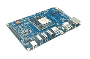
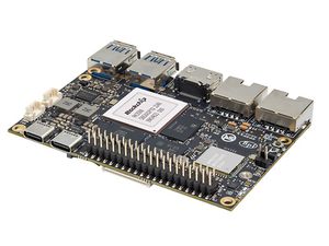
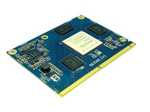
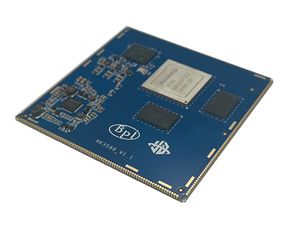
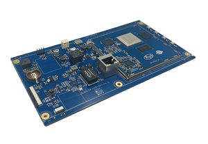
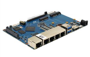
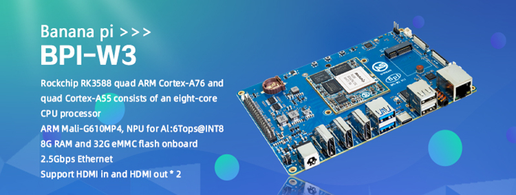
The Banana Pi BPI-W3 single board computer is designed and developed by bananapi team for professional and enterprise users, powered by Rockchip RK3588 SoC quad ARM Cortex-A76 and quad Cortex-A55 consists of an eight-core CPU processor with dynamic frequency scaling up to 2.4GHz. Embedded high -performance 3D and 2D image acceleration module, AI accelerator NPU with a built -in 6 TOPS computing power.
BPI-W3 up to 32GB 64bit LPDDR4X ram, up to 8K@60 HDMI OUT, HDMI IN, MIPI DSI, MIPI CSI, 3.5mm jack with mic, USB Port, 2.5GbE LAN, PCIe 3.0 x4, PCIe 2.0x2, 40-pin expansion header, RTC,POE,SD card, DC power,typec.
Key Features
- Rockchip RK3588 quad ARM Cortex-A76 and quad Cortex-A55 consists of an eight-core CPU processor
- ARM Mali-G610 MP4,
- NPU for AI : 6Tops@INT8
- 8G RAM and 32G eMMC flash onboard
- 2.5Gbps Ethernet
- support HDMI in and HDMI out * 2
Getting Start
Hardware
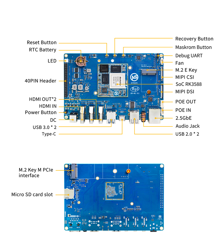
Hardware interface
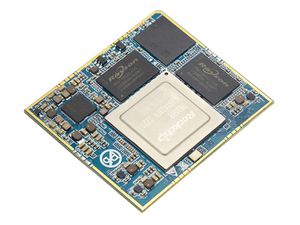
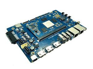
BPI-3588-LGA Core board
Banana Pi BPI-W3 base on BPI-RK3588 Core board and development Kit use BPI-RK3588-LGA core board. so you can easy to do new design with BPI-W3, just need to development a new base board.
BPI-3588-LGA core board uses the Rockchip RK3588 flagship chip,integrating a 6Tops NPU and a high-performance quad-core Mali-G610 MP4 GPU. It adopts LGA 506pin package method, which can expand a variety of display interfaces and industrial application interfaces. With open baseboard design materials and open-source SDKs, it can be efficiently developed. It supports multiple operating systems such as Android, Ubuntu, Debian, and Buildroot. It provides robust, stable, reliable, and expandable product support for various AI application scenarios, and is widely applicable to fields such as edge computing, artificial intelligence,cloud computing, VR/AR, blockchain, smart security, intelligent industrial control, and smart home.
BPI-3588-LGA spec
| SOC | Rockchip RK3588 | |
| CPU | Quad Core [email protected] +Quad Core [email protected], 8nm | |
| GPU | ARM Mali-G610 MP4 GPU,Support OpenGL ES3.2 / OpenCL 2.2 / Vulkan1.1 | |
| NPU | 6 TOPS@INT8,Support INT4/INT8/INT16 mixed operation Support framework switching of TensorFlow/MXNet/PyTorch/Caffe | |
| ISP | 48-Megapixel ISP,It implements a lot of algorithm accelerators, such as HDR, 3A, LSC, 3DNR, 2DNR, sharpening, dehaze, fisheye correction, gamma correction and so on. | |
| Encode&Decode | Decode:8K@60fps H.265/VP9/AVS2,8K@30fps H.264 AVC/MVC, 4K@60fps AV1, 1080P@60fps MPEG-2/-1/VC-1/VP8
Encode:8K@30fps H.265 / H.264 | |
| RAM | 4GB/8GB/16GB(up to 32GB)64-bit LPDDR4/LPDDR4x, Defalut LPDDR4x 8GB | |
| Flash | 16GB/32GB/64GB/128GB/256GB eMMC, support MicroSD card slot, Defaut eMMC 32GB | |
| Operating Systems | Android 12.0, Ubuntu 20.04, Ubuntu 22.04, Debian11, Buildroot, Armbian, Kylin OS | |
| Power supply | 4.0V | |
| Interface Type | LGA 506pin | |
| Size | 45mm×50mm×4.5mm(top: 2.2mm+PCB: 1.2mm +bottom: 1.1mm) | |
| Operating temperature | 0℃ ~ 70℃ | |
| Storage temperature | -20℃ ~ 70℃ |
Function parameter
| Category | Function | quantity | parameter | |
|---|---|---|---|---|
| Video Input Interface | MIPI DC(DPHY/CPHY) combo PHY | 2 |
|
Support camera input combination:
|
| MIPI CSI DPHY | 4 |
| ||
| DVP | ≤1 |
| ||
| HDMI RX | 1 |
| ||
| Display interface | HDMI/eDP TX interface | ≤2 |
| |
| DP TX | 2 |
| ||
| MIPI DSI | 2 |
| ||
| BT.1120 video output | ≤1 |
| ||
| Audio Interface | I2S | ≤4 |
| |
| SPDIF | ≤2 |
| ||
| PDM | ≤2 |
| ||
| Network interface | GMAC | ≤2 |
| |
| Connectivity interface | SDIO | ≤1 |
| |
| USB 2.0 Host | 2 |
| ||
| SATA | ≤3 |
|
Combo PIPE PHY0 support one of the following interfaces
Combo PIPE PHY1 support one of the following interfaces
Combo PIPE PHY2 support one of the following interfaces
| |
| USB3.1 Gen1 | ≤3 |
| ||
| PCIe2.1 | ≤3 |
| ||
| PCIe3.0 | ≤4 |
| ||
| SPI | ≤5 |
| ||
| I2C | ≤9 |
| ||
| UART | ≤10 |
| ||
| CAN | ≤3 |
| ||
| Others interface | GPIO | Multiple |
| |
| ADC | ≤8 |
| ||
| PWM | ≤16 |
| ||
BPI-W3 Hardware spec
| SOC | RockChip RK3588 |
| CPU | Quad Core A76+ Quad Core A55 ,use 8nm , 2.4GHz |
| GPU | ARM Mali-G610 MP4 GPU,Support OpenGL ES3.2 / OpenCL 2.2 / Vulkan1.1, 450 GFLOPS |
| NPU | 6 TOPS,Support INT4/INT8/INT16 mixed operation,Support framework switching of TensorFlow/MXNet/PyTorch/Caffe |
| Encode&Decode | encode:8K@60fps H.265/VP9/AVS2、8K@30fps H.264 AVC/MVC、4K@60fps AV1、1080P@60fps MPEG-2/-1/VC-1/VP8 ,decode:8K@30fps H.265 / H.264 |
| Ram | 4GB/8GB/16GB(up to 32GB)64bit LPDDR4/LPDDR4x/LPDDR5,Defalut LPDDR4 8GB |
| Flash | 16GB/32GB/64GB/128GB/256GB eMMC,support MicroSD card slot,Defaut :32GB |
| M2 Key M | The interface supports extension SSD |
| network | 2.5G network port(RLT8125BS) |
| video output | 2 x HDMI2.1(just one support 8K@60fps or 4K@120fps,other support 4K@60fps),1 x MIPI-DSI(4K@60fps),1 x DP1.4(8K@30fps), |
| video input | 1 x 4Lanes MIPI CSI / 2 x 2lanes MIPI CSI,1 x HDMI RX2.0 |
| Voice | 2 x HDMI voice output ,1 x DP1.4 voice output,1 x headphone (es8316) |
| Wireless | M2 E key interface support sdio、pcie、usb BT&wifi(AP6256,Intel AX210) |
| USB | 2 x USB3.1,2 x USB2.0,1x USB-C(DP1.4(8K@30fps)/OTG/PD fast charging) |
| Others | Fan、RTC、LED、debug |
| Button | Power Button、Reset Button、 Recovery Button、Root Button |
| GPIO | 40 x GPIO(UART、SPI、I2C、I2S、PWM、ADC、 GPIO、 5V power 、3.3V power) |
| Power | DC 12V/2.5A bore diameter 2.5mm,support USB Type-C PD 2.0 ,9V/2A, 12V/2A, 15V/2A,Support 12V POE power supply |
| System | Android 12.0、Ubuntu、Debian11、Buildroot、Kylin Linux |
| Size | 148 mm × 100.5mm |
| operating temperature | -10℃ ~ 70℃ |
| storage temperature | -20℃ ~ 70℃ |
40 PIN GPIO
| GPIO number | Function8 | Function7 | Function6 | Function5 | Function4 | Function3 | Function2 | Function1 | Pin# |
|---|---|---|---|---|---|---|---|---|---|
| +3.3V | 1 | ||||||||
| 139 | I2S1_SDO2_M0 | I2C7_SDA_M3 | UART8_CTSN_M0 | PWM15_IR_M1 | CAN1_TX_M1 | GPIO4_B3 | 3 | ||
| 138 | I2S1_SDO1_M0 | I2C7_SCL_M3 | UART8_RTSN_M0 | PWM14_M1 | CAN1_RX_M1 | GPIO4_B2 | 5 | ||
| 115 | SPI1_CS1_M1 | I2C8_SDA_M4 | UART7_CTSN_M1 | PWM15_IR_M0 | GPIO3_C3 | 7 | |||
| GND | 9 | ||||||||
| 113 | SPI1_CLK_M1 | UART7_RX_M1 | GPIO3_C1 | 11 | |||||
| 111 | SPI1_MOSI_M1 | I2C3_SCL_M1 | GPIO3_B7 | 13 | |||||
| 112 | SPI1_MISO_M1 | I2C3_SDA_M1 | UART7_TX_M1 | GPIO3_C0 | 15 | ||||
| +3.3V | 17 | ||||||||
| 42 | SPI0_MOSI_M2 | UART4_RX_M2 | GPIO1_B2 | 19 | |||||
| 41 | SPI0_MISO_M2 | GPIO1_B1 | 21 | ||||||
| 43 | SPI0_CLK_M2 | UART4_TX_M2 | GPIO1_B3 | 23 | |||||
| GND | 25 | ||||||||
| 150 | SPI3_CLK_M0 | I2C0_SDA_M1 | PWM7_IR_M3 | GPIO4_C6 | 27 | ||||
| 63 | UART1_CTSN_M1 | PWM15_IR_M3 | GPIO1_D7 | 29 | |||||
| 47 | SPDIF_TX_M0 | UART1_RX_M1 | PWM13_M2 | GPIO1_B7 | 31 | ||||
| 103 | PWM8_M0 | GPIO3_A7 | 33 | ||||||
| 110 | I2S2_LRCK_M1 | UART3_RX_M1 | PWM13_M0 | CAN1_TX_M0 | GPIO3_B6 | 35 | |||
| 37 | |||||||||
| GND | 39 |
| Pin# | Function1 | Function2 | Function3 | Function4 | Function5 | Function6 | Function7 | Function8 | GPIO number |
|---|---|---|---|---|---|---|---|---|---|
| 2 | +5.0V | ||||||||
| 4 | +5.0V | ||||||||
| 6 | GND | ||||||||
| 8 | GPIO0_B5 | UART2_TX_M0 | I2C1_SCL_M0 | I2S1_MCLK_M1 | 13 | ||||
| 10 | GPIO0_B6 | UART2_RX_M0 | I2C1_SDA_M0 | I2S1_SCLK_M1 | 14 | ||||
| 12 | GPIO3_B5 | CAN1_RX_M0 | PWM12_M0 | UART3_TX_M1 | I2S2_SCLK_M1 | 109 | |||
| 14 | GND | ||||||||
| 16 | GPIO3_A4 | 100 | |||||||
| 18 | GPIO4_C4 | PWM5_M2 | SPI3_MISO_M0 | 148 | |||||
| 20 | GND | ||||||||
| 22 | SARADC_IN4 | ||||||||
| 24 | GPIO1_B4 | UART7_RX_M2 | SPI0_CS0_M2 | 44 | |||||
| 26 | GPIO1_B5 | UART7_TX_M2 | SPI0_CS1_M2 | 45 | |||||
| 28 | GPIO4_C5 | PWM6_M2 | I2C0_SCL_M1 | SPI3_MOSI_M0 | 149 | ||||
| 30 | GND | ||||||||
| 32 | GPIO3_C2 | PWM14_M0 | UART7_RTSN_M1 | I2C8_SCL_M4 | SPI1_CS0_M1 | 114 | |||
| 34 | GND | ||||||||
| 36 | GPIO3_B1 | PWM2_M1 | UART2_TX_M2 | 105 | |||||
| 38 | GPIO3_B2 | PWM3_IR_M1 | UART2_RX_M2 | I2S2_SDI_M1 | 106 | ||||
| 40 | GPIO3_B3 | UART2_RTSN | I2S2_SDO_M1 | 107 |
MIPI CSI
0.5mm FPC Connector
Pin# MIPI-CSI Description 1,4,7,10,13,16,19,21,24,25,26,27,32,33 GND Power Ground & Signal Ground 2 MIPI_CSI0_RX_D3N MIPI RX Lane3 iuput N 3 MIPI_CSI0_RX_D3P MIPI RX Lane3 iuput P 5 MIPI_CSI0_RX_D2N MIPI RX Lane2 iuput N 6 MIPI_CSI0_RX_D2P MIPI RX Lane2 iuput P 8 MIPI_CSI0_RX_CLK1N MIPI RX Clock iuput N 9 MIPI_CSI0_RX_CLK1P MIPI RX Clock iuput P 11 MIPI_CSI0_RX_D1N MIPI RX Lane1 iuput N 12 MIPI_CSI0_RX_D1P MIPI RX Lane1 iuput P 14 MIPI_CSI0_RX_D0N MIPI RX Lane0 iuput N 15 MIPI_CSI0_RX_D0P MIPI RX Lane0 iuput P 17 MIPI_CSI0_RX_CLK0N MIPI RX Clock iuput N 18 MIPI_CSI0_RX_CLK0P MIPI RX Clock iuput P 20 MIPI_CAM3_CLKOUT 1.8V, CLock ouput for Sensor 22 MIPI_CAM1_CLKOUT 1.8V, CLock ouput for Sensor 23 MIPI_CSI0_PDN0_H(GPIO1_B0) 1.8V, GPIO 24 I2C3_SCL_M0_MIPI 1.8V, I2C Clock, pulled up to 1.8V with 2.2K on w3 25 I2C3_SDA_M0_MIPI 1.8V, I2C Clock, pulled up to 1.8V with 2.2K on w3 26 MIPI_CSI0_PDN1_H(GPIO1_A7) 1.8V, GPIO 27 CM_RST_L(GPIO4_A0) 3.3V, GPIO 28,29 VCC_RX 3.3V Power ouput 30,31 VCC_5V0 5V Power ouput
MIPI DSI
0.5mm FPC Connector (J23)
Pin# MIPI-DSI Description 1,4,7,10,13,16,27,33,34 GND Power and Signal Ground 2 MIPI_DPHY1_TX_D0N MIPI1 TX Lane0 ouput N 3 MIPI_DPHY1_TX_D0P MIPI1 TX Lane0 ouput P 5 MIPI_DPHY1_TX_D1N MIPI1 TX Lane1 ouput N 6 MIPI_DPHY1_TX_D1P MIPI1 TX Lane1 ouput P 8 MIPI_DPHY1_TX_CLKN MIPI1 TX Clock ouput N 9 MIPI_DPHY1_TX_CLKP MIPI1 TX Clock ouput P 11 MIPI_DPHY1_TX_D2N MIPI1 TX Lane2 ouput N 12 MIPI_DPHY1_TX_D2P MIPI1 TX Lane2 ouput P 14 MIPI_DPHY1_TX_D3N MIPI1 TX Lane3 ouput N 15 MIPI_DPHY1_TX_D3P MIPI1 TX Lane3 ouput P 17 LCD_PWM (PWM2_M2/GPIO4_C2) 1.8V, GPIO/PWM 18,19 VCC3V3_LCD 3.3V Power ouput 20 LCD_RESET (GPIO2_C1) 1.8V, GPIO 21 /NC No Connection 22 LCD_BL_EN (GPIO3_A1) 3.3V, GPIO 23 I2C6_SCL_M0 1.8V, I2C Clock, pulled up to 1.8V with 2.2K on w3 24 I2C6_SDA_M0 1.8V, I2C Data, pulled up to 1.8V with 2.2K on w3 25 TP_INT (GPIO0_D3) 1.8V, GPIO 26 TP_RST (GPIO0_C6) 1.8V, GPIO 28,29 VCC5V0_LCD 5V Power ouput 31,32 VCC_1V8 1.8V Power ouput
Debug UART
3.3V level signals, 1500000bps
Pin# Assignment Description 1 UART2_RX_M0 intput 2 UART2_TX_M0 output 3 GND 0V
PoE In
1.25mm Connector
Pin# Assignment Description 1 VC1 TX1 2 VC2 RX1 3 VC3 TX2 4 VC4 RX2
PoE Out
2.0mm Connector
Pin# Assignment Description 1 VDD_POE 12V Power ouput 2 VDD_POE 12V Power ouput 3 GND Ground pin 4 GND Ground pin
Fan
1.25mm Connector
Pin# Assignment Description 1 VCC_5V0 5V Power ouput 2 VCC_5V0 5V Power ouput 3 PWM1_M0/GPIO0_C0 1.8V, PWM/GPIO
Resources
Source code
- Banana Pi linux-5.10.110 kernel BSP Source code on github :https://github.com/BPI-SINOVOIP/BPI-W3-BSP
- Armsom github source code :https://github.com/ArmSoM/armsom-w3-bsp
Documents
- Rockchip RK3588 datasheet
- Baidu cloud: https://pan.baidu.com/s/1GeskKfLFwjgmz0pgt7sICg?pwd=8888 (pincode:8888)
- Google drive: https://drive.google.com/drive/folders/1l1YmUdBaLuDkJma3CYZJWjYug9D-jV_4?usp=sharing
- Banana PI BPI-W3 SCH, DXF, SMD file
- Baidu cloud: https://pan.baidu.com/s/1ETL7U4R54Cd5cDg8usp-JQ?pwd=pb48 (pincode:8888)
- Google drive: https://drive.google.com/drive/folders/1d_vtW5aDH3dPAco-dHIwm16r25JUYWS8?usp=sharing
- Banana Pi BPI-W3 coare board 3588-LGA Core board all pin list file(5.core board (LGA) pin List)
- Baidu cloud: https://pan.baidu.com/s/1ZqDRkk0NVEjpHxsQNHbleQ?pwd=8888 (pincode:8888)
- Google drive: https://docs.google.com/spreadsheets/d/1yj6fLbJET5cLjJG-cD3R5_b7S4umTFXI/edit?usp=sharing&ouid=101692257577438398584&rtpof=true&sd=true
- Banana Pi Core board design for RK3588 : BPI-RK3588 Core board and development Kit
- Rockchip RK3588 datasheet :https://drive.google.com/file/d/1KAq1_kKqPtkq8Vlq-h_yUPUZLrgqSKHI/view?usp=sharing
- Banana Pi BPI-W3 RK3588 NPU6T AI RKNN Toolkit2 and RKNPU2 demo :https://www.youtube.com/watch?v=AEU87YUZz8Y
- BPI-W3 Rk3588 development github blog: https://github.com/ArmSoM/Embedded-Technology-Blog
- BPI-W3 ubuntu20.04 Linux system adaptation is complete:https://www.youtube.com/watch?v=xVDkWv_Q9xY
Image Release
Android
- BPI-W3_armsom-w3-emmc-android12-rkr12-20231103.img
- Baidu cloud: https://pan.baidu.com/s/1rAfTRARQRDwaZnulPOu0Fg?pwd=8888 (pincode:8888)
- Google drive: https://drive.google.com/file/d/1y_tEuc0rslUtNn4SVZoyPTh9tAqAcKp4/view?usp=sharing
- BPI-W3_armsom-w3-emmc-android12-TV-rkr12-20230525.img
- Baidu cloud:https://pan.baidu.com/s/1p8gOK3gNTN-f0Fxb6c6CFw?pwd=8888 (pincode:8888)
- Google drive: https://drive.google.com/file/d/1knzU875x6FQdYNef3DSaFExbMn6IXjf4/view?usp=sharing
Linux
Armbian
Ubuntu
- ubuntu-22.04.3-preinstalled-desktop-arm64-bpi-w3_armsom-w3.img
- Baidu Cloud: https://pan.baidu.com/s/1lKyEvNJXKkf13xwDg1e4Hw?pwd=8888 (pincode:8888)
- Google Drive: https://drive.google.com/drive/folders/162vkWVjWJCsPRG7XjONzCIkdPkro5zY1?usp=sharing
- ubuntu-22.04.3-preinstalled-server-arm64-bpi-w3_armsom-w3.img
- Baidu cloud: https://pan.baidu.com/s/1cqbpgk5ykp_-1uv9ZpxoZg?pwd=8888 (pincode:8888)
- Google drive: https://drive.google.com/drive/folders/1-GxlXelKY11b-sbiNARzA0DZ-bb328l-?usp=sharing
Debian
- BPI-W3_armsom-w3-debian-bullseye-xfce4-arm64-20231204.img
- Baidu cloud: https://pan.baidu.com/s/1OB6qzCmwhaXTnabs0_jmeQ?pwd=8888 (pincode:8888)
- Google drive: https://drive.google.com/drive/folders/1E9ynf6LSThnb7HLDC09IqAJDdOo4TWK4?usp=sharing
BPI-W3 Tools
- Baidu cloud : https://pan.baidu.com/s/1SD3shbfQui4N19IVTXpmXQ?pwd=8888 Pincode:8888
- Google drive: https://drive.google.com/file/d/1v1ixTDcjOqBPn6eyiNSH5yOBNWPUA8Ig/view?usp=sharing
Easy to buy sample
- SINOVOIP Aliexpress shop: https://www.aliexpress.us/item/3256805306000586.html?gatewayAdapt=glo2usa4itemAdapt&_randl_shipto=US
- BPI Aliexpress shop : https://www.aliexpress.com/item/1005005492412383.html?spm=5261.ProductManageOnline.0.0.44927197rtt5Zg
- Taobao shop : https://item.taobao.com/item.htm?spm=a213gs.success.result.1.7a637a8674R4AD&id=714475598378
- OEM&ODM:[email protected]
