Getting Started with BPI-W3
Contents
- 1 Introduction
- 2 specifications
- 3 Android
- 4 Linux
Introduction


Before starting to use your ArmSoM-W3 get the following items ready
- PI-W3
- power supply(choose one of three)
- 12 volt @2/3A via DC Power
- USB C PD Charger (15W & above)
- 12 volt PoE
- If you wish to boot from sd card:MicroSD Card/TF Card: Class 10 or Above, minimum 8GB SDHC
specifications
Android
Prepare
- 1. Good Type-C data cable for image download into EMMC
- 2. Usb to ttl cable if you need debug, default baudrate is 1500000.
- 3. Windows or Linux PC.
- 4. Download the Android, and confirm that the md5 checksum is correct before flashing.
Note: The below picture is for BPI-W3's Debug Connecting, the red usb cable is Type-C data cable for image download, the three colors usb to ttl cable is linux serial console, please install CH340E's USB convert serial driver.

Install Whole Image with Usb Download Tool
Windows Driver install
1. Download and install Rockchip USB driver

2. Download Rockchip USB Download Tool for EMMC upgrade
- This tool defaults language is Chinese. you can change it to English after extract the package. Open RKDevTool_Release_v2.84/config.ini with an text editor (like notepad). The starting lines are:
 #Language Selection: Selected=1(Chinese); Selected=2(English)
 [Language]
 Kinds=2
 Selected=2
 LangPath=Language\
3. Open RKDevTool.exe, Switch to the “upgrade firmware” page. Press the “firmware” button to open the image file to be upgraded. The upgrade tool displays detailed firmware information.
Note: Because Linux's release image is very large, So you need wait for a long time when Software open and analysis the image file.

4. Disconnect the power adapter , connect the type-c cable to the bpi-w3 and PC.
5. There have two usb download mode for image upgrade.
- Uboot Usb Download Mode (loader mode)
- It's supposed to use this way if board already flashed a bootable uboot before.
- Maskrom Usb Download Mode
- Press the Recovery button or Maskrom button beside 3pin uart header and hold, connect the power adapter or press the RST button if power adapter already connected, about two seconds later, release the button. PC will Identify the device if RK usb driver installed correctly.
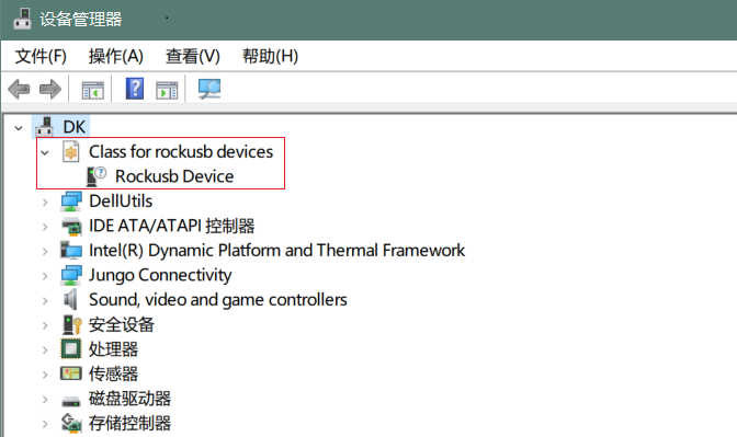

- The download tool also show the download mode if device connected.
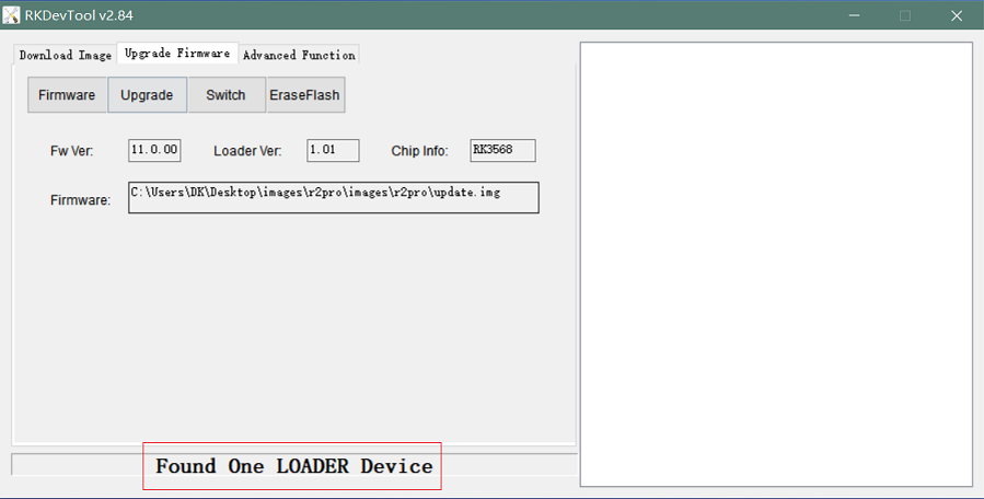


6. Press the “upgrade” button to start the upgrade.

7: If the upgrade fails, you can try to erase the Emmc by pressing the EraseFlash button first, and then upgrade image again.

Linux
Prepare
- 1. Usb to ttl cable if you need debug, default baudrate is 1500000.
- 2. Download the Linux, and confirm that the md5 checksum is correct before flashing.
Install Image to SDcard 1
NOTE: Use this method for Ubuntu and Armbian images.
- Install Image with Balena Etcher.
- Balena Etcher is an opensource GUI flash tool by Balena, Flash OS images to SDcard or USB drive.
- 1.Click on "Flash from file" to select image.
- 2.Click on "Select target" to select USB device.
- 3.Click on "Flash!" Start burning.

Install Image to SDcard 2
NOTE: Debian images use this method.
- 1. Download Rockchip SDDiskTool.
- 2. Insert card reader to Windows PC, 8GB sdcard size at least.
- 3. Run SD_Firmware_Tool, check the “SD card startup” box and select the correct removable disk device, Choose firmware image, then Click Create button to make it and wait until it is finshed.

Build Linux BSP Source Code
- 1. Get Linux source code
$ git clone https://github.com/BPI-SINOVOIP/BPI-W3-BSP
- 2. Build the Linux BSP Source code
Dual Display
  Note: All linux Image suuport dual display HDMI and MIPI-DSI together, MIPI-DSI only support 1200x1920.
  Note: HDMI Display

Note: MIPI-DSI panel Display

Wlan&BT
- J14 M.2 KEY E Slot is used for connect Wlan&BT adapter, default image support RTL8822CE(PCIE+USB) and RTL8822CS(SDIO+UART).
Connect WiFi
Command line connection
- 1.Open WiFi:
sudo nmcli r wifi on
- 2.List wifi list:
sudo nmcli dev wifi list
- 3.Connect to wifi
- SSID is BPI, password is bananapi, using the wlan0 interface as an example.
sudo nmcli dev wifi connect BPI password bananapi ifname wlan0
Command line graphical connection
- Enter graphics configuration
sudo nmtui
- Move the keyboard arrow keys to Active a connection and press Enter to enter wifi settings
- Move the arrow keys to the wifi you want to connect to and press Enter
- If you are connecting to an unconnected hotspot with a password, you will enter the password input interface.
- If you want to disconnect from wifi, press the Enter key when connected to disconnect.
Desktop connection
- Open WiFi, select the one you want to connect to, click and enter the password.
Static network
nmtui
- Set the ip address before the static address
sudo ifconfig
enP4p65s0: flags=4163<UP,BROADCAST,RUNNING,MULTICAST> mtu 1500
        inet 192.168.10.100 netmask 255.255.255.0 broadcast 192.168.10.255
        ether 92:be:6d:d5:e7:b4 txqueuelen 1000 (Ethernet)
        RX packets 23758 bytes 1774543 (1.6 MiB)
        RX errors 0 dropped 80 overruns 0 frame 0
        TX packets 67013 bytes 3879463 (3.6 MiB)
        TX errors 0 dropped 0 overruns 0 carrier 0 collisions 0
        device interrupt 155
- If you want to successfully set a static address, you need to pay attention to whether the IP address you want to set is occupied by other devices. You can use ping to set the static address. If there is data returned, it proves that the IP address is occupied by other devices.
- The following are detailed steps
- 1.Enter graphics configuration
nmtui
- Move the keyboard arrow keys to Edit a connection and press Enter to enter the wifi settings.
- 2.Select the network you want to edit, here we take eth0 as an example
- Enter to see the default configuration of the network

- 3.Need to set IPV4 CONFIGURATION to Manual
- 4.Then move the cursor to show and press enter to enter detailed configuration
Here we take the IP address 192.168.10.13 and the gateway 192.168.10.1 as an example.
NOTE:The IP address and gateway need to be configured according to your actual network conditions. If you copy the configuration here, there is a high chance that your product will not be able to connect to the Internet. Junior developers recommend changing the static IP to a dynamically obtained IP.
- How to obtain the gateway
- 1.Set the network to automatically obtain IP
- 2. After successfully obtaining the IP, use the command
route
- result
 root@w3:/home/armsom# route
 Kernel IP routing table
 Destination Gateway Genmask Flags Metric Ref Use Iface
 default 192.168.10.1 0.0.0.0 UG 100 0 0 enP4p65s0
 192.168.10.0 0.0.0.0 255.255.255.0 U 100 0 0 enP4p65s0
- 3.Gateway is our gateway, use the following command
route-n
- result
 root@lubancat:~# route -n
 Kernel IP routing table
 Destination Gateway Genmask Flags Metric Ref Use Iface
 default 192.168.10.1 0.0.0.0 UG 100 0 0 enP4p65s0
 192.168.10.0 0.0.0.0 255.255.255.0 U 100 0 0 enP4p65s0
- You can see our gateway address ---- 192.168.10.1
- 192.168.10.13/24 where /24 represents the mask 255.255.255.0,
- DNS servers Nationwide DNS–>114.114.114.114 Global DNS–>8.8.8.8
- Search domain can inherit DNS servers settings. Multiple DNS servers and search domains can be set.
- After setting up, you can move to the back and click OK to complete the setting.
- After completing the settings, you need to activate the settings for the network to take effect. Click Activate a connection to enter the connection, press enter once to cancel the connection, and press enter again to reconnect.
- The IP after the re -connection becomes the IP we set up
 root@w3:/home/armsom# ip addr
    lo: <LOOPBACK,UP,LOWER_UP> mtu 65536 qdisc noqueue state UNKNOWN group default qlen 1000
     link/loopback 00:00:00:00:00:00 brd 00:00:00:00:00:00
     inet 127.0.0.1/8 scope host lo
        valid_lft forever preferred_lft forever
    enP4p65s0: <BROADCAST,MULTICAST,UP,LOWER_UP> mtu 1500 qdisc mq state UP group default qlen 1000
     link/ether 92:be:6d:d5:e7:b4 brd ff:ff:ff:ff:ff:ff permaddr be:87:f6:b4:e5:ad
     inet 192.168.10.13/24 brd 192.168.10.255 scope global noprefixroute enP4p65s0
        valid_lft forever preferred_lft forever
    wlP2p33s0: <NO-CARRIER,BROADCAST,MULTICAST,UP> mtu 1500 qdisc mq state DOWN group default qlen 1000
     link/ether 2c:05:47:8e:4a:6c brd ff:ff:ff:ff:ff:ff
    wlan1: <NO-CARRIER,BROADCAST,MULTICAST,UP> mtu 1500 qdisc mq state DOWN group default qlen 1000
     link/ether 2e:05:47:8e:4a:6c brd ff:ff:ff:ff:ff:ff
- We can also use ping baidu.com to check if we have successfully connected to the external network
 root@w3: $ ping baidu .com
 PING baidu.com (110.242.68.66) 56( 84) bvtes of data.
 64 bytes from 110.242.68.66 (110.242.68.66): icmp seg=1 ttl=50 time=41.9 ms
 64 bytes from 110.242.68.66 (110.242.68.66): icmp seg=2 ttl=50 time=54.2 ms
 64 bytes from 110.242.68.66 (110.242.68.66): icmp seg=3 ttl=50 time=45.8 ms
nmcli
- Taking enP4p65s0 as an example, this step is similar to editing the network in nmtui, except that it changes from a graphical interface to a command line operation, with various names in the command line. This is only a partial introduction, and those interested can explore it on their own.
- 1.First, list the configuration of the connection. eth0 is currently connected to Wired connection 1
 root@w3:/home/armsom# nmcli c s
 NAME                UUID                                  TYPE      DEVICE
 Wired connection 1  e01f934d-7fae-344f-90bf-e2483db3f3e5  ethernet  enP4p65s0
 armsom                d3d9a6ff-9c9c-44f8-a366-6a69af1edd1a  wifi      --
 armsom 1              7867c3af-dca2-4e9a-9721-a20f7a0e1b46  wifi      --
- 2.Then modify Wired connection 1
- Static IP settings
 sudo nmcli c modify 'Wired connection 1'

 sudo nmcli c m 'Wired connection 1' ipv4.address 192.168.10.13/24
 sudo nmcli c m 'Wired connection 1' ipv4.method manual
 sudo nmcli c m 'Wired connection 1' ipv4.gateway 192.168.10.1
 sudo nmcli c m 'Wired connection 1' ipv4.dns 8.8.8.8
 sudo nmcli c m 'Wired connection 1' +ipv4.dns 114.114.114.114
 sudo nmcli c m 'Wired connection 1' ipv6.method disabled
 sudo nmcli c m 'Wired connection 1' connection.autoconnect yes
- Note that IPv4.Address must be modified first before you can modify ipv4.Method!
- 3.Activate configuration
sudo nmcli c up ifname eth0
- 4.After configuration, the IP changed
 root@w3:~$ ip addr
   lo: <LOOPBACK,UP,LOWER_UP> mtu 65536 qdisc noqueue state UNKNOWN group default qlen 1000
     link/loopback 00:00:00:00:00:00 brd 00:00:00:00:00:00
     inet 127.0.0.1/8 scope host lo
        valid_lft forever preferred_lft forever
   enP4p65s0: <BROADCAST,MULTICAST,UP,LOWER_UP> mtu 1500 qdisc mq state UP group default qlen 1000
     link/ether 92:be:6d:d5:e7:b4 brd ff:ff:ff:ff:ff:ff permaddr be:87:f6:b4:e5:ad
     inet 192.168.10.14/24 brd 192.168.10.255 scope global noprefixroute enP4p65s0
        valid_lft forever preferred_lft forever
   wlP2p33s0: <NO-CARRIER,BROADCAST,MULTICAST,UP> mtu 1500 qdisc mq state DOWN group default qlen 1000
     link/ether 2c:05:47:8e:4a:6c brd ff:ff:ff:ff:ff:ff
   wlan1: <NO-CARRIER,BROADCAST,MULTICAST,UP> mtu 1500 qdisc mq state DOWN group default qlen 1000
     link/ether 2e:05:47:8e:4a:6c brd ff:ff:ff:ff:ff:ff
Ethernet
ArmSoM-w3 is configured with one 2.5G Ethernet interface. You can connect ArmSoM-w3 to the network using a network cable (one end is connected to an external network port or a route). The ArmSoM-w3 automatically configures the network for your Internet access.
Check that the Ethernet is working by using the ifconfig command, which displays network card eth0 or enP4p65s0, along with the Ethernet IP address. In addition, you can use the ping tool to test network connectivity.
ifconfig
ping www.google.com
If the network cable is connected, no IP address is assigned to the node.
dhclient eth0
or
dhclient enP4p65s0
HDMI RX
The ArmSoM-w3 uses an hdmi_in port built into the rk3588 chip,You can use the v4l2 command to test the hdmi in interface.
View all video nodes
ls /dev/video*
Look for the rk hdmirx device
Run the v4l2-ctl -d command to specify the vidoe node. Run the -D command to view the node information. Check the rk_hdmirx device using the Driver name.
# v4l2-ctl -d /dev/video0 -D
Driver Info:
Driver name : rk_hdmirx
Card type : rk_hdmirx
Bus info : fdee0000.hdmirx-controller
Driver version : 5.10.66
Capabilities : 0x84201000
Video Capture Multiplanar
Streaming
Extended Pix Format
Device Capabilities
Device Caps : 0x04201000
Video Capture Multiplanar
Streaming
Extended Pix Format
Query resolution and image format
To query the current resolution and image format:
# v4l2-ctl -d /dev/video17 --get-fmt-video
Format Video Capture Multiplanar:
Width/Height : 3840/2160
Pixel Format : 'NV16'
Field : None
Number of planes : 1
Flags : premultiplied-alpha, 000000fe
Colorspace : Unknown (1025fcdc)
Transfer Function : Unknown (00000020)
YCbCr Encoding : Unknown (000000ff)
Quantization : Default
Plane 0 :
Bytes per Line : 3840
Size Image : 16588800
Grab image file
Save the image file to the device, adb pull to the PC, and view it through 7yuv and other tools:
v4l2-ctl --verbose -d /dev/video17 \
--set-fmt-video=width=3840,height=2160,pixelformat='NV16' \
--stream-mmap=4 --stream-skip=3 \
--stream-to=/data/4k60_nv16.yuv \
--stream-count=5 --stream-poll
Querying the HDMI RX status
Query the current status of HDMI RX, including signal locking, image format, Timings information, Pixl Clk, etc.
# cat /d/hdmirx/status
status: plugin
Clk-Ch:Lock Ch0:Lock Ch1:Lock Ch2:Lock
Ch0-Err:0 Ch1-Err:0 Ch2-Err:0
Color Format: YUV422 Store Format: YUV422 (8 bit)
Mode: 3840x2160p60 (4400x2250) hfp:172 hs:92 hbp:296 vfp:8 vs:10 vbp:72
Pixel Clk: 594024000
Camera
1. MIPI-CSI The camera uses the IMX415 module,After the camera module is connected and powered on, you can view the startup log.
root@linaro-alip:/# dmesg | grep imx415
[    2.547754] imx415 3-001a: driver version: 00.01.08
[    2.547767] imx415 3-001a:  Get hdr mode failed! no hdr default
[    2.547819] imx415 3-001a: Failed to get power-gpios
[    2.547826] imx415 3-001a: could not get default pinstate
[    2.547831] imx415 3-001a: could not get sleep pinstate
[    2.547850] imx415 3-001a: supply dvdd not found, using dummy regulator
[    2.547918] imx415 3-001a: supply dovdd not found, using dummy regulator
[    2.547945] imx415 3-001a: supply avdd not found, using dummy regulator
[    2.613843] imx415 3-001a: Detected imx415 id 0000e0
[    2.613890] rockchip-csi2-dphy csi2-dphy0: dphy0 matches m00_b_imx415 3-001a:bus type 5
[   18.386174] imx415 3-001a: set fmt: cur_mode: 3864x2192, hdr: 0
[   18.389067] imx415 3-001a: set exposure(shr0) 2047 = cur_vts(2250) - val(203)
The kernel assigns device information description files to the camera.
grep "" /sys/class/video4linux/v*/name | grep mainpath
/sys/class/video4linux/video11/name:rkisp_mainpath
Verify the functions of the camera
Grab a picture
# v4l2-ctl -d /dev/video11 --set-fmt-video=width=3840,height=2160,pixelformat=NV12 --stream-mmap=3 --stream-skip=60 --stream-to=/tmp/cif73.out --stream-count=3 --stream-poll
Display on desktop using gst-launch-1.0
# gst-launch-1.0 v4l2src device=/dev/video11 ! video/x-raw,format=NV12,width=3840,height=2160, framerate=30/1 ! xvimagesink

2. USB3.0 Camera
After connecting the usb3.0 camera, open the Qt V4L2 test Utility application for testing

Then open the video node: video21:

Then click the camera button, you will see the camera screen:

NPU usage
DEMO video: https://www.youtube.com/watch?v=y7mYxn3rq0U
Prepare tools
1. Use the Ubuntu18.04 / Ubuntu20.04 operating system (OS).
2. An W3-PRO board
Preparation procedure
First make sure you have docker installed on your Ubuntu system,If not, refer to the Internet installation tutorial
We provide the source code and the docker image of the installed environment:docker image
Create a rknpu folder on the PC server and copy the firmware to the folder
rknpu/rknn-toolkit2-1.4.0/docker$ ls
md5sum.txt  rknn-toolkit2-1.4.0-cp36-docker.tar.gz  rknn-toolkit2-1.4.0-cp38-docker.tar.gz
Run the following command to run the docker image. After the Docker image is run, the bash environment of the image is displayed
docker run -t -i --privileged -v /dev/bus/usb:/dev/bus/usb rknn-toolkit2:1.4.0-cp38 /bin/bash
Map examples code into a Docker environment by attaching "-v <host src folder>:<image dst folder>"Parameters, such as:
docker run -t -i --privileged -v /dev/bus/usb:/dev/bus/usb -v /your/rknn-toolkit2-1.x.x/examples:/examples rknn-toolkit2:1.x.x /bin/bash
The code is synchronized after mapping
The rknn service needs to run on the development board
BOARD ARCH corresponds to the aarch64 directory on 64-bit Linux systems and to the armhf directory on 32-bit systems
1. adb push all files in Linux/rknn server/${B0ARD_ ARCH}/usr/bin/ to /usr/bin
2. adb push Linux/librknn api/${BOARD ARCH}/ librknrnt. so to /usr/1ib
3. Access the serial port terminal of the board and run the following command
chmod +x /usr/bin/rknn server
chmod +X /usr/bin/start_ rknn.sh
chmod +X /usr/bin/restart rknn.sh
restart_ rknn. sh
run program
Execute adb devices in the docker image first, remembering the adb ID number
Go to /examples/onnx/yolov5 and change test.py
ret = rknn.init_runtime(target='rk3588', device_id=DEVICE_ID, perf_debug=True,eval_mem=True)
outputs = rknn.inference(inputs=[img])
ret = rknn.eval_perf(inputs=[img], is_print=True)
cv2.imwrite("result.jpg", img_1)
The above four functions are not added
Run python3 test.py
LED
On BPI-W3 three-color LED is configured as LED class device. When the blue LED is not active a green LED will show to indicate the board has power. You can control the behavior mode of the blue LED by writing to /sys/class/leds/blue:status/trigger. By default only root users can write to the device. The default mode of the blue LED is heartbeat.
linaro@linaro-alip:/home/linaro# sudo su // linaro password
root@linaro-alip:/home/linaro# echo timer > /sys/class/leds/blue:status/trigger
root@linaro-alip:/home/linaro# echo activity > /sys/class/leds/blue:status/trigger
You can use cat on the trigger property to list all the available LED modes. The value in brackets is the currently active mode.
root@linaro-alip:/home/linaro# cat /sys/class/leds/blue:status/trigger
none rfkill-any rfkill-none kbd-scrolllock kbd-numlock kbd-capslock kbd-kanalock kbd-shiftlock kbd-altgrlock kbd-ctrllock kbd-altlock kbd-shiftllock kbd-shiftrlock kbd-ctrlllock kbd-ctrlrlock tcpm-source-psy-4-0022-online mmc2 mmc1 timer oneshot disk-activity disk-read disk-write ide-disk mtd nand-disk heartbeat backlight gpio cpu cpu0 cpu1 cpu2 cpu3 cpu4 cpu5 cpu6 cpu7 mmc0 [activity] default-on transient flash torch panic netdev rfkill0
In the None mode, writing to /sys/class/leds/blue:status/brightness can manually control the status of the blue LED.
root@linaro-alip:/home/linaro# echo none > /sys/class/leds/blue:status/trigger
root@linaro-alip:/home/linaro# echo 1 > /sys/class/leds/blue:status/brightness
root@linaro-alip:/home/linaro# echo 0 > /sys/class/leds/blue:status/brightness
red light is the same, class device /sys/class/leds/red:status/trigger
RTC Device
BPI-W3 is equipped with one RTC IC hym8563
Firstly, plug in RTC battery to give power to RTC IC. Please note that we should keep the RTC battery in the RTC connector.
Secondly,Check whether the driver is successfully loaded.
root@linaro-alip:~# dmesg | grep rtc
[    3.149263] rtc-hym8563 6-0051: rtc information is valid
[    3.154624] rtc-hym8563 6-0051: registered as rtc0
[    3.155646] rtc-hym8563 6-0051: setting system clock to 2021-01-01T12:00:05 UTC (1609502405)
Finally, check whether you can view and set the time.
root@linaro-alip:~# hwclock -r
2022-08-07 13:38:24.370866+00:00
root@linaro-alip:~# date
2022年 08月 07日 星期日 13:38:41 UTC
root@linaro-alip:~# hwclock -w
Audio
View sound cards in the system.
root@linaro-alip:/# aplay -l
**** List of PLAYBACK Hardware Devices ****
card 0: rockchipdp0 [rockchip,dp0], device 0: rockchip,dp0 spdif-hifi-0 [rockchip,dp0 spdif-hifi-0]
 Subdevices: 1/1
 Subdevice #0: subdevice #0
card 1: rockchipes8316 [rockchip-es8316], device 0: fe470000.i2s-ES8316 HiFi es8316.7-0011-0 [fe470000.i2s-ES8316 HiFi es8316.7-0011-0]
  Subdevices: 1/1
  Subdevice #0: subdevice #0
card 3: rockchiphdmi0 [rockchip-hdmi0], device 0: rockchip-hdmi0 i2s-hifi-0 [rockchip-hdmi0 i2s-hifi-0]
  Subdevices: 1/1
  Subdevice #0: subdevice #0
card 4: rockchiphdmi1 [rockchip-hdmi1], device 0: rockchip-hdmi1 i2s-hifi-0 [rockchip-hdmi1 i2s-hifi-0]
  Subdevices: 1/1
  Subdevice #0: subdevice #0
Specify the sound card to play audio fiile.
aplay -D hw:0,0 /mnt/test.wav
MIC
root@linaro-alip:/root# arecord -D hw:1,0 -f S16_LE -t wav -c2 -r 16000 -d 3 t.wav
Recording WAVE 't.wav' : Signed 16 bit Little Endian, Rate 16000 Hz, Stereo
root@linaro-alip:/root# aplay t.wav
Playing WAVE 't.wav' : Signed 16 bit Little Endian, Rate 16000 Hz, Stereo
Storage device
Supports three types of storage devices
microSD card
/dev/mmcblk1
eMMC
/dev/mmcblk0
NVME M.2 SDD
root@linaro-alip:/home/linaro# mkdir temp
root@linaro-alip:/home/linaro# mount /dev/nvme0n1 temp
FAN
echo 0 > /sys/devices/platform/fd8b0010.pwm/pwm/pwmchip*/export
echo 10000 > /sys/devices/platform/fd8b0010.pwm/pwm/pwmchip*/pwm0/period
echo 5000 > /sys/devices/platform/fd8b0010.pwm/pwm/pwmchip*/pwm0/duty_cycle
echo inversed  > /sys/devices/platform/fd8b0010.pwm/pwm/pwmchip*/pwm0/polarity
echo 1 > /sys/devices/platform/fd8b0010.pwm/pwm/pwmchip*/pwm0/enable
#echo 0 > /sys/devices/platform/fd8b0010.pwm/pwm/pwmchip*/pwm0/enable
Overlays
The device tree Overlays make it possible to support multiple hardware configurations with a single kernel, without the need to explicitly load or mask kernel modules.
Ubuntu 22.04 Mirror Enable Overlay
- The path for storing the overlay file of Ubuntu 22.04 image on the board side is:/boot/firmware/dtbs/rockchip/overlay/*.dtbo
- Find the keyword "overlays=" in the /boot/firmware/ubuntuEnv.txt file. The following is an example of using two overlay layers for BPI-W3.
overlays=bananapi-w3-camera-imx415-4k bananapi-w3-display-mipi-dsi
- After editing, restart the device to change the overlay settings.
Armbian Mirror Enable Overlay
- The path for storing the overlay file of Armbian image on the board side is:/boot/dtbs/rockchip/overlay/*.dtbo
- Find the keyword "overlays=" in the /boot/armbianEnv.txt file. The following is an example of using two overlay layers for BPI-W3.
overlays=bananapi-w3-camera-imx415-4k bananapi-w3-display-mipi-dsi
- After editing, restart the device to change the overlay settings.
Others
NPU usage
Prepare tools
1. Use the Ubuntu18.04 / Ubuntu20.04 operating system (OS).
2. An W3-PRO board
Preparation procedure
First make sure you have docker installed on your Ubuntu system,If not, refer to the Internet installation tutorial
We provide the source code and the docker image of the installed environment:docker image
Create a rknpu folder on the PC server and copy the firmware to the folder
rknpu/rknn-toolkit2-1.4.0/docker$ ls
md5sum.txt  rknn-toolkit2-1.4.0-cp36-docker.tar.gz  rknn-toolkit2-1.4.0-cp38-docker.tar.gz
Run the following command to run the docker image. After the Docker image is run, the bash environment of the image is displayed
docker run -t -i --privileged -v /dev/bus/usb:/dev/bus/usb rknn-toolkit2:1.4.0-cp38 /bin/bash
Map examples code into a Docker environment by attaching "-v <host src folder>:<image dst folder>"Parameters, such as:
docker run -t -i --privileged -v /dev/bus/usb:/dev/bus/usb -v /your/rknn-toolkit2-1.x.x/examples:/examples rknn-toolkit2:1.x.x /bin/bash
The code is synchronized after mapping
The rknn service needs to run on the development board
BOARD ARCH corresponds to the aarch64 directory on 64-bit Linux systems and to the armhf directory on 32-bit systems
1. adb push all files in Linux/rknn server/${B0ARD_ ARCH}/usr/bin/ to /usr/bin
2. adb push Linux/librknn api/${BOARD ARCH}/ librknrnt. so to /usr/1ib
3. Access the serial port terminal of the board and run the following command
 chmod +x /usr/bin/rknn server
 chmod +X /usr/bin/start_ rknn.sh
 chmod +X /usr/bin/restart rknn.sh
 restart_ rknn. sh
run program
Execute adb devices in the docker image first, remembering the adb ID number
Go to /examples/onnx/yolov5 and change test.py
ret = rknn.init_runtime(target='rk3588', device_id=DEVICE_ID, perf_debug=True,eval_mem=True)
outputs = rknn.inference(inputs=[img])
ret = rknn.eval_perf(inputs=[img], is_print=True)
cv2.imwrite("result.jpg", img_1)
The above four functions are not added
Run python3 test.py