Difference between revisions of "BPI-Leaf-S3"
(→Hardware Spec) |
(→Introduction) |
||
| (82 intermediate revisions by 3 users not shown) | |||
| Line 1: | Line 1: | ||
[[zh:BPI-Leaf-S3 开发板]] | [[zh:BPI-Leaf-S3 开发板]] | ||
| + | |||
| + | |||
= Introduction = | = Introduction = | ||
| + | [[File:Leaf-S3-incline-front.jpg|thumb|[[BPI-Leaf-S3]] with ESP32-S3]] | ||
| + | [[File:Leaf-S3-incline-back.jpg|thumb|[[BPI-Leaf-S3]] with ESP32-S3]] | ||
| + | [[File:BPI-Centi-S3_2.jpg|thumb|[[BPI-Centi-S3]] with ESP32-S3 front]] | ||
| + | [[File:PICO-1000-7.jpg|thumb|[[BPI-PicoW-S3 ]]with ESP32-S3]] | ||
| + | [[File:Smart-01-03.gif|thumb|[[BPI-Smart ]]with ESP8266]] | ||
| + | [[File:Webduino_gif.gif|thumb|[[BPI-Bit]] with ESP32]] | ||
| + | [[File:BPI-AI_1.JPG|thumb|[[BPI-AI]] Kendryte K210 RISC-V]] | ||
| + | [[File:ESP32_6.JPG|thumb|[[BPI-UNO32]] with ESP32 design]] | ||
| − | The Banana Pi Leaf series | + | The Banana Pi BPI-Leaf-S3 is a series of low-powered microcontrollers designed for IoT development and Maker DIY board.It supports 2.4 GHz Wi-Fi and Bluetooth® LE dual-mode wireless communication, the peripheral is compatible with low-power hardware design, and the power consumption is only 10uA in deep sleep mode. |
| − | |||
| − | |||
| − | + | The main controller supports two power supply inputs: USB and external 3.7V lithium battery, both can be interchangable freely. The battery could also be charged while USB is plugged in. Compact size, various interface, easy to use, and can be directly applied to low-power IoT projects. | |
| − | + | In terms of programming, the Leaf-S3 supports ESP-IDF, Arduino, micropython and other methods. | |
| − | + | The IO pins on BPI-Leaf-S3 are identical to the Espressif ESP32-S3-DevKitC-1, developers can add peripherals that are supported by DevKitC-1 onto the BPI-Leaf-S3, and can also combine it onto a breadboard. | |
| − | + | [[File:BPI-Leaf-S3_banner.jpg]] | |
== Key Features == | == Key Features == | ||
* ESP32-S3,Xtensa® 32 bit LX7 | * ESP32-S3,Xtensa® 32 bit LX7 | ||
| − | * | + | * Extereal FLASH 8MB |
| + | * In-packge PSRAM 2MB | ||
* Ultra-low power 10uA | * Ultra-low power 10uA | ||
* 2.4G WIFI ,Bluetooth 5 ,Bluetooth mesh | * 2.4G WIFI ,Bluetooth 5 ,Bluetooth mesh | ||
* GPIO , ADC , TOUCH , PWM , I2C , SPI , RMT , I2S , UART , LCD,CAMERA ,USB , JTAG | * GPIO , ADC , TOUCH , PWM , I2C , SPI , RMT , I2S , UART , LCD,CAMERA ,USB , JTAG | ||
| − | * 1* | + | * 1* SH 1mm 4-Pin Socket, support I2C |
* 1 * USB Type-C | * 1 * USB Type-C | ||
| − | * 1 * | + | * 1 * MX 1.25mm 2-Pin Socket,support USB charging |
* 1 * Neopixel LED | * 1 * Neopixel LED | ||
| + | |||
| + | == ESP32-S3-DevKitC-1, BPI-Leaf-S3 Comparison == | ||
| + | |||
| + | {| class="wikitable" | ||
| + | |- | ||
| + | ! Dev Board | ||
| + | ! BPI-Leaf-S3 | ||
| + | ! ESP32-S3-DevKitC-1 | ||
| + | |- | ||
| + | | GPIO Pins | ||
| + | | 36 | ||
| + | | 36 | ||
| + | |- | ||
| + | | 3.3v Pins | ||
| + | | 3 | ||
| + | | 3 | ||
| + | |- | ||
| + | | 5v Pins | ||
| + | | 1 | ||
| + | | 1 | ||
| + | |- | ||
| + | | GND Pins | ||
| + | | 4 | ||
| + | | 4 | ||
| + | |- | ||
| + | | ARGB LEDs | ||
| + | | 1 on GPIO48 | ||
| + | | 1 on GPIO48 | ||
| + | |- | ||
| + | | Chip Internal USB | ||
| + | | USB-C Connector x 1 | ||
| + | | MicroUSB Connector x 1 | ||
| + | |- | ||
| + | | UART TTL to USB | ||
| + | | None | ||
| + | | CP2102-MicroUSB Connector x 1 | ||
| + | |- | ||
| + | | External Battery Socket | ||
| + | | 3.7v Li-ion Battery dock | ||
| + | | None | ||
| + | |- | ||
| + | | Battery Charging | ||
| + | | 500mA Charging Current | ||
| + | | None | ||
| + | |- | ||
| + | | JST SH 1mm 4-Pin Socket | ||
| + | | 1 | ||
| + | | None | ||
| + | |} | ||
| + | |||
| + | The amount, numeric order, and spacing of IO pins on BPI-Leaf-S3 are identical to the Espressif ESP32-S3-DevKitC-1. | ||
| + | |||
| + | The BPI-Leaf-S3 dev board no longer equips traditional UART TTL to USB converter chip and its dedicated USB port. This is due to the ESP32-S3 chip's internal USB function were improved, supporting CDC-ACM virtual serial port and JTAG interface, which is capable of software development and firmware management feature, that makes the external converter chip redundant. | ||
| + | |||
| + | Compared to ESP32-S3-DevKitC-1 dev board, the BPI-Leaf-S3 adds an external battery socket and a charging circuit, capable of charging the battery via USB. When a 3.7v battery is connected, unplugging the USB will not cause the program to break, making it fit for multiple applications. | ||
| + | |||
| + | BPI-Leaf-S3 dev board is equipped with an I²C 4 pin dock, this stabalizes connection to other I²C peripherals. This dock is not only restricted to I²C connection, any module that requires a 3.3v pin, a GND pin, one or two data pin can also be connected to the Leaf-S3 via this 4 pin dock. | ||
| + | |||
| + | ==Espressif ESP32-S3== | ||
| + | |||
| + | ESP32-S3 is a dual-core XTensa LX7 MCU, capable of running at 240 MHz. Apart from its 512 KB of internal SRAM, it also comes with integrated 2.4 GHz, 802.11 b/g/n Wi-Fi and Bluetooth 5 (LE) connectivity that provides long-range support. It has 45 programmable GPIOs and supports a rich set of peripherals. Compared with ESP32, it supports larger, high-speed octal SPI flash, and PSRAM with configurable data and instruction cache. | ||
| + | |||
| + | What follows is a description of the most important features of ESP32-S3. | ||
| + | |||
| + | * Wi-Fi + Bluetooth 5 (LE) Wireless Connectivity: ESP32-S3 supports a 2.4 GHz Wi-Fi (802.11 b/g/n) with 40 MHz of bandwidth support. The Bluetooth Low Energy subsystem supports long range through Coded PHY and advertisement extension. It also supports higher transmission speed and data throughput, with 2 Mbps PHY. Both Wi-Fi and BLE have superior RF performance that is maintained even at high temperatures. | ||
| + | |||
| + | * AI Acceleration Support: ESP32-S3 has additional support for vector instructions in the MCU, which provides acceleration for neural network computing and signal processing workloads. The software libraries for the above-mentioned optimized functions will become available very soon, in the form of updates to ESP-WHO and ESP-Skainet. | ||
| + | |||
| + | * Rich Set of IO Peripherals: ESP32-S3 has 44 programmable GPIOs, namely 10 more GPIOs than those of ESP32. ESP32-S3 supports all the commonly-used peripherals, such as SPI, I2S, I2C, PWM, RMT, ADC and UART, SD/MMC host and TWAITM. In total, 14 GPIOs can be configured as capacitive touch input for HMI applications. Apart from all these peripherals, however, ESP32-S3 is also equipped with an ultra-low-power (ULP) core that supports multiple low-power modes in a variety of such use-cases. | ||
| + | |||
| + | * Security:ESP32-S3 provides all the necessary security requirements for building securely connected devices, without requiring any external components. It supports AES-XTS-based flash encryption and RSA-based secure boot. In addition, ESP32-S3 has a digital signature peripheral and an HMAC module, which provide functionality that is similar to the hardware secure element, thus protecting the private or symmetric key from software attacks and identity theft. ESP32-S3 also has a “World Controller” peripheral that provides two fully-isolated execution environments, which enable the implementation of a trusted-execution environment or a privilege-separation scheme. | ||
| + | |||
| + | ==Getting Start== | ||
| + | |||
| + | *[https://bpi-steam.com/Leaf_S3_doc/en/ Getting Started with BPI-Leaf-S3] | ||
= Hardware = | = Hardware = | ||
| Line 31: | Line 115: | ||
== Hardware sketch map == | == Hardware sketch map == | ||
| − | [[File:Leaf-S3_board.png| | + | [[File:Leaf-S3_board.png|800px]] |
== Hardware Spec == | == Hardware Spec == | ||
| Line 45: | Line 129: | ||
| 240MHz MAX | | 240MHz MAX | ||
|- | |- | ||
| − | | | + | | Operating Temperature |
| -40℃~+85℃ | | -40℃~+85℃ | ||
|- | |- | ||
| Line 52: | Line 136: | ||
|- | |- | ||
| Internal SRAM | | Internal SRAM | ||
| − | | | + | | 512 KB |
|- | |- | ||
| − | | | + | | Onboard FLASH ROM |
| 8MB | | 8MB | ||
|- | |- | ||
| − | | | + | | In-packge PSRAM |
| − | | | + | | 2MB |
|- | |- | ||
| WIFI | | WIFI | ||
| Line 105: | Line 189: | ||
| 1,CDC-ACM ,JTAG | | 1,CDC-ACM ,JTAG | ||
|- | |- | ||
| − | | Temperature | + | | Temperature Sensor |
| − | | | + | | 1,ranging from -20 °C to 110 °C |
|- | |- | ||
| SD/MMC | | SD/MMC | ||
| Line 124: | Line 208: | ||
|- | |- | ||
| Timers | | Timers | ||
| − | | 4 × 54-bit general-purpose timers.1 × 52-bit system timer.3 × watchdog timers | + | | 4 × 54-bit general-purpose timers. 1 × 52-bit system timer. 3 × watchdog timers |
|- | |- | ||
| External crystal oscillator | | External crystal oscillator | ||
| Line 142: | Line 226: | ||
|- | |- | ||
| Maximum discharge current | | Maximum discharge current | ||
| − | | [email protected] | + | | [email protected] DC/DC |
|- | |- | ||
| USB charge | | USB charge | ||
| − | | | + | | Support |
|- | |- | ||
| Maximum charging current | | Maximum charging current | ||
| 500mA | | 500mA | ||
|- | |- | ||
| − | | LED | + | | Neopixel LED |
| 1 | | 1 | ||
|} | |} | ||
| Line 162: | Line 246: | ||
! colspan="2" style=" background-color:#ffcb2f;" | BPI-Leaf-S3 Dimensions | ! colspan="2" style=" background-color:#ffcb2f;" | BPI-Leaf-S3 Dimensions | ||
|- | |- | ||
| − | | | + | | Pin spacing |
| 2.54mm | | 2.54mm | ||
|- | |- | ||
| − | | | + | | Mounting hole spacing |
| 23mm/ 62.25mm | | 23mm/ 62.25mm | ||
|- | |- | ||
| − | | | + | | Mounting hole size |
| − | | | + | | bore 2mm/outside 3mm |
|- | |- | ||
| − | | | + | | Motherboard size |
| 26 × 65.25(mm)/1.02 x 2.57(inches) | | 26 × 65.25(mm)/1.02 x 2.57(inches) | ||
|- | |- | ||
| − | | | + | | board thickness |
| 1.2mm | | 1.2mm | ||
|} | |} | ||
| − | + | The pin spacing is breadboard compatible for easy application debugging. | |
| − | == | + | == Peripheral Pin Configurations == |
{| class="wikitable" | {| class="wikitable" | ||
| Line 186: | Line 270: | ||
! colspan="3" style=" background-color:#ffcb2f;" | BPI-Leaf-S3 GPIO Pin define | ! colspan="3" style=" background-color:#ffcb2f;" | BPI-Leaf-S3 GPIO Pin define | ||
|- style="background-color:#32cb00;" | |- style="background-color:#32cb00;" | ||
| − | | | + | | Peripheral Interface |
| − | | | + | | Signal |
| − | | | + | | Pin |
|- | |- | ||
| rowspan="2" | ADC | | rowspan="2" | ADC | ||
| Line 197: | Line 281: | ||
| GPIO 11~20 | | GPIO 11~20 | ||
|- | |- | ||
| − | | | + | | Touch sensor |
| TOUCH1~14 | | TOUCH1~14 | ||
| GPIO 1~14 | | GPIO 1~14 | ||
| Line 215: | Line 299: | ||
|- | |- | ||
| rowspan="14" | UART | | rowspan="14" | UART | ||
| − | | colspan="2" style="font-style:italic;color:#9b9b9b;" | | + | | colspan="2" style="font-style:italic;color:#9b9b9b;" | The pins are assigned by default, and can be redefined to any GPIO |
|- | |- | ||
| style="background-color:#ffffc7;" | U0RXD_in | | style="background-color:#ffffc7;" | U0RXD_in | ||
| Line 224: | Line 308: | ||
|- | |- | ||
| U0DSR_in | | U0DSR_in | ||
| − | | | + | | any GPIO |
|- | |- | ||
| style="background-color:#ffffc7;" | U0TXD_out | | style="background-color:#ffffc7;" | U0TXD_out | ||
| Line 233: | Line 317: | ||
|- | |- | ||
| U0DTR_out | | U0DTR_out | ||
| − | | | + | | any GPIO |
|- | |- | ||
| style="background-color:#ffffc7;" | U1RXD_in | | style="background-color:#ffffc7;" | U1RXD_in | ||
| Line 242: | Line 326: | ||
|- | |- | ||
| U1DSR_in | | U1DSR_in | ||
| − | | | + | | any GPIO |
|- | |- | ||
| style="background-color:#ffffc7;" | U1TXD_out | | style="background-color:#ffffc7;" | U1TXD_out | ||
| Line 251: | Line 335: | ||
|- | |- | ||
| U1DTR_out | | U1DTR_out | ||
| − | | | + | | any GPIO |
|- | |- | ||
| style="background-color:#9aff99;" | U2 | | style="background-color:#9aff99;" | U2 | ||
| − | | style="background-color:#9aff99;" | | + | | style="background-color:#9aff99;" | any GPIO |
|- | |- | ||
| I2C | | I2C | ||
| − | | colspan="2" | | + | | colspan="2" | any GPIO |
|- | |- | ||
| PWM | | PWM | ||
| − | | colspan="2" | | + | | colspan="2" | any GPIO |
|- | |- | ||
| I2S | | I2S | ||
| − | | colspan="2" | | + | | colspan="2" | any GPIO |
|- | |- | ||
| LCD | | LCD | ||
| − | | colspan="2" | | + | | colspan="2" | any GPIO |
|- | |- | ||
| CAMERA | | CAMERA | ||
| − | | colspan="2" | | + | | colspan="2" | any GPIO |
|- | |- | ||
| RMT | | RMT | ||
| − | | colspan="2" | | + | | colspan="2" | any GPIO |
|- | |- | ||
| SPI0/1 | | SPI0/1 | ||
| − | | colspan="2" | | + | | colspan="2" | Used for FLASH and PSRAM |
|- | |- | ||
| SPI2/3 | | SPI2/3 | ||
| − | | colspan="2" | | + | | colspan="2" | any GPIO |
|- | |- | ||
| − | | | + | | Pulse counter |
| − | | colspan="2" | | + | | colspan="2" | any GPIO |
|- | |- | ||
| rowspan="8" | USB OTG | | rowspan="8" | USB OTG | ||
| D- | | D- | ||
| − | | GPIO | + | | GPIO 19(on-chip PHY) |
|- | |- | ||
| D+ | | D+ | ||
| − | | GPIO | + | | GPIO 20(on-chip PHY) |
|- | |- | ||
| VP | | VP | ||
| − | | GPIO | + | | GPIO 42(external PHY) |
|- | |- | ||
| VM | | VM | ||
| − | | GPIO | + | | GPIO 41(external PHY) |
|- | |- | ||
| RCV | | RCV | ||
| − | | | + | | GPIO21(external PHY) |
|- | |- | ||
| OEN | | OEN | ||
| − | | GPIO | + | | GPIO 40(external PHY) |
|- | |- | ||
| VPO | | VPO | ||
| − | | GPIO | + | | GPIO 39(external PHY) |
|- | |- | ||
| VMO | | VMO | ||
| − | | | + | | GPIO38(external PHY) |
|- | |- | ||
| − | | rowspan=" | + | | rowspan="7" | USB Serial/JTAG |
| D- | | D- | ||
| − | | GPIO | + | | GPIO 19(on-chip PHY) |
|- | |- | ||
| D+ | | D+ | ||
| − | | GPIO | + | | GPIO 20(on-chip PHY) |
|- | |- | ||
| VP | | VP | ||
| − | | GPIO | + | | GPIO 42(external PHY) |
|- | |- | ||
| VM | | VM | ||
| − | | GPIO | + | | GPIO 41(external PHY) |
|- | |- | ||
| OEN | | OEN | ||
| − | | GPIO | + | | GPIO 40(external PHY) |
|- | |- | ||
| VPO | | VPO | ||
| − | | GPIO | + | | GPIO 39(external PHY) |
|- | |- | ||
| VMO | | VMO | ||
| − | | | + | | GPIO38(external PHY) |
|- | |- | ||
| SD/MMC | | SD/MMC | ||
| − | | colspan="2" | | + | | colspan="2" | any GPIO |
|- | |- | ||
| MCPWM | | MCPWM | ||
| − | | colspan="2" | | + | | colspan="2" | any GPIO |
|- | |- | ||
| TWAI | | TWAI | ||
| − | | colspan="2" | | + | | colspan="2" | any GPIO |
|- | |- | ||
| − | | | + | | Neopixel LED |
| colspan="2" | GPIO 48 | | colspan="2" | GPIO 48 | ||
|} | |} | ||
| + | |||
| + | = Software = | ||
| + | |||
| + | == Espressif ESP-IDF == | ||
| + | |||
| + | [[File:Esp-idf-logo.png | 800px]] | ||
| + | |||
| + | ESP-IDF is the development framework for Espressif SoCs supported on Windows, Linux and macOS. | ||
| + | |||
| + | It is recommend that developers install ESP-IDF via IDE. | ||
| + | |||
| + | * [https://github.com/espressif/idf-eclipse-plugin/blob/master/README.md GitHub: ESP-IDF Eclipse Plugin README] | ||
| + | * [https://marketplace.visualstudio.com/items?itemName=espressif.esp-idf-extension ESP-IDF VSCode Extension] | [https://github.com/espressif/vscode-esp-idf-extension/blob/master/docs/tutorial/toc.md GitHub: README ] | [https://www.youtube.com/watch?v=Lc6ausiKvQM youtube: Quick User Guide for the ESP-IDF VSCode Extension] | ||
| + | |||
| + | Or install manually based on operating system: | ||
| + | |||
| + | * [https://docs.espressif.com/projects/esp-idf/en/latest/esp32s3/get-started/windows-setup.html Standard Setup of Toolchain for Windows] | ||
| + | * [https://docs.espressif.com/projects/esp-idf/en/latest/esp32s3/get-started/linux-macos-setup.html Standard Toolchain Setup for Linux and macOS] | ||
| + | |||
| + | API: | ||
| + | |||
| + | * [https://docs.espressif.com/projects/esp-idf/en/latest/esp32s3/api-reference/index.html#api-reference ESP-IDF API Reference Docs] | ||
| + | * [https://docs.espressif.com/projects/esp-idf/en/latest/esp32s3/api-guides/index.html#api-guides ESP-IDF API Guides] | ||
| + | |||
| + | To enable your BPI-Leaf-S3 device to flash via USB-CDC. | ||
| + | |||
| + | There are two ways to enter Bootloader mode: | ||
| + | |||
| + | # Connect it to the computer via USB, hold BOOT button, press RST button once, then release BOOT button. | ||
| + | # Hold BOOT button while disconnected to power, connect to PC via USB, then release BOOT button. | ||
| + | |||
| + | The chip controls GPIO0 via BOOT button to choose between reset or cold boot. | ||
| + | |||
| + | Confirm the port of your BPI-Leaf-S3 device via device manager, it might display different port if you are on different modes. | ||
| + | |||
| + | *ESP-DL (deep learning) Auto-Generating Model Deployment Project using TVM: https://docs.espressif.com/projects/esp-dl/en/latest/esp32/tutorials/deploying-models-through-tvm.html | ||
| + | |||
| + | == MicroPython == | ||
| + | |||
| + | [[File:Mircopython.png | 800px]] | ||
| + | |||
| + | Regardless of the programmer is a beginner or not, MicroPython is considered to be less difficult to develop than other MCU programming languages. | ||
| + | |||
| + | Its code is easy to understand compared to other programming languages, and it has various resources accumulated over the years by the open source community. | ||
| + | |||
| + | Just like Python, it has strong vitality and application value. | ||
| + | |||
| + | * [[ micropython_operating_env | Building MicroPython Operating Environment ]] | ||
| + | * [[ micropython_firmware | MicroPython Firmware Download]] | ||
| + | |||
| + | '''BPI-Steam resources''' | ||
| + | * [https://bpi-steam.com/Leaf_S3_doc/en/MicroPython/Environment.html MicroPython runtime environment setup] | ||
| + | * [https://bpi-steam.com/Leaf_S3_doc/en/MicroPython/Firmware.html Micropython firmware download and burning] | ||
| + | * [https://bpi-steam.com/Leaf_S3_doc/en/MicroPython/Basic.html Basic use case] | ||
| + | * [https://bpi-steam.com/Leaf_S3_doc/en/MicroPython/ESPNOW.html ESP-NOW use case] | ||
| + | |||
| + | '''Forum resources''' | ||
| + | * [https://forum.banana-pi.org/t/bpi-leaf-s3-esp-now-on-micropython-easy-to-implement-networking-communication/15481 BPI-Leaf-S3 , ESP-NOW on MicroPython, easy to implement networking communication] | ||
| + | * [https://forum.banana-pi.org/t/bpi-leaf-s3-oled-displays-potentiometer-voltage-and-progress-bar/13718 BPI-Leaf-S3 OLED displays potentiometer voltage and progress bar] | ||
| + | * [https://forum.banana-pi.org/t/banana-pi-bpi-leaf-s3-with-esp32-s3-use-potentiometer-to-control-neopixel-steplessly/13703 BPI-Leaf-S3 with ESP32-S3, use potentiometer to control neopixel steplessly] | ||
| + | * [https://forum.banana-pi.org/t/banana-pi-bpi-leaf-s3-with-esp32-s3-use-key-interrupts-to-control-neopixel/13660 BPI-Leaf-S3 with ESP32-S3, use key interrupts to control neopixel] | ||
| + | * [https://forum.banana-pi.org/t/banana-pi-bpi-leaf-s3-with-esp32-s3-micropython-neopixel-show/13661 BPI-Leaf-S3 with ESP32-S3 & microPython Neopixel show] | ||
| + | * [https://forum.banana-pi.org/t/banana-pi-bpi-leaf-s3-micropython-getting-started-blink-led-on-bread-board/13634 BPI-Leaf-S3 microPython getting started, blink LED on bread board] | ||
| + | * [https://forum.banana-pi.org/t/bpi-leaf-s3-micropython-display-web-clock-on-oled-screen/13324 BPI-Leaf-S3+MicroPython: Display Web Clock on OLED screen] | ||
| + | * [https://forum.banana-pi.org/t/banana-pi-bpi-leaf-s3-micropython-use-adc-measuring-potentiometer-to-control-the-motor/13273 BPI-Leaf-S3+MicroPython:Use ADC measuring potentiometer to control the motor] | ||
| + | * [https://forum.banana-pi.org/t/banana-pi-bpi-leaf-s3-micropython-with-tb6612fng-pwm-motor/13259 Banana Pi BPI-Leaf-S3 MicroPython with TB6612FNG PWM Motor] | ||
| + | * [https://forum.banana-pi.org/t/making-iot-programming-easy-using-micropython-on-bpi-leaf-s3/13248 Making IoT programming easy,using MicroPython on BPI-Leaf-S3] | ||
| + | |||
| + | == CircuitPython == | ||
| + | |||
| + | [[File:CircuitPython_Repo_header_logo.jpg | 800px]] | ||
| + | |||
| + | CircuitPython is a programming language designed to simplify experimenting and learning to code on low-cost microcontroller boards. | ||
| + | |||
| + | CircuitPython programming with Mu editor is the easiest way to get started. Install the software and connect the device to start using it. | ||
| + | |||
| + | [https://circuitpython.org/board/bpi_leaf_s3/ BPI-Leaf-S3 CircuitPython Download Page] | ||
| + | |||
| + | [https://codewith.mu/ Mu Editor] | ||
| + | |||
| + | '''How to install tinyUF2 firmware:''' | ||
| + | |||
| + | To enable your BPI-Leaf-S3 device to flash via USB-CDC. | ||
| + | |||
| + | Connect it to the computer via USB, hold BOOT button, press RST button once, then release BOOT button. | ||
| + | |||
| + | In the Install, Repair, or Update UF2 Bootloader section at the bottom of the page, follow its instructions to download and install tinyUF2 firmware. | ||
| + | |||
| + | '''How to install CircuitPython firmware:''' | ||
| + | |||
| + | Click the DOWNLOAD .UF2 NOW button on the right side of the page to download the firmware to the local, and then copy it to the disk in BPI-Leaf-S3 UF2 Bootloader mode, and it can be used after automatic reset. | ||
| + | |||
| + | '''Supported by the adafruit/circuitpython GitHub repository''' | ||
| + | |||
| + | https://github.com/adafruit/circuitpython/pull/6904 | ||
| + | |||
| + | '''Supported by the adafruit/tinyuf2 GitHub repository''' | ||
| + | |||
| + | https://github.com/adafruit/tinyuf2/pull/196 | ||
| + | |||
| + | == Arduino == | ||
| + | |||
| + | [[File:Arduino_logo_1200x350.png | 800px]] | ||
| + | |||
| + | Arduino is an open source embedded software and hardware development platform for users to create interactive embedded projects. | ||
| + | |||
| + | * [https://www.arduino.cc/en/software Arduino IDE download link] | [https://docs.espressif.com/projects/arduino-esp32/en/latest/installing.html#installing Install and configure the Arduino-ESP32 runtime environment] | ||
| + | * [https://github.com/BPI-STEAM/BPI-Leaf-S3-Doc/blob/main/Example/Arduino GitHub: BPI-Leaf-S3 Arduino Getting Started] | ||
| + | * [https://docs.espressif.com/projects/arduino-esp32/en/latest/libraries.html#apis Arduino-ESP32 APIs] | ||
| + | |||
| + | '''Supported by the arduino-esp32 GitHub repository''' | ||
| + | |||
| + | https://github.com/espressif/arduino-esp32/pull/7345 | ||
| + | |||
| + | The board has been merged into the master branch. | ||
| + | |||
| + | = Resources = | ||
| + | |||
| + | * [https://github.com/BPI-STEAM/BPI-Leaf-S3-Doc/blob/main/sch/BPI-Leaf-S3-Chip-V0.1A.pdf BPI-Leaf-S3 schematic diagram PDF] | ||
| + | |||
| + | * [https://www.espressif.com/sites/default/files/documentation/esp32-s3_datasheet_en.pdf ESP32-S3 Datasheet] | ||
| + | |||
| + | * [https://www.espressif.com/sites/default/files/documentation/esp32-s3_technical_reference_manual_en.pdf ESP32-S3 Technical Reference Manual] | ||
| + | |||
| + | =Easy to buy sample= | ||
| + | |||
| + | * BIPAI Aliexpress shop:https://www.aliexpress.com/item/1005004701866550.html? | ||
| + | * SINOVOIP Aliexpress shop : https://www.aliexpress.com/item/1005004428945296.html?spm=5261.ProductManageOnline.0.0.48af4edfYbyEoI | ||
| + | * Taobao shop : https://item.taobao.com/item.htm?spm=a2126o.success.0.0.29034831FGnLQW&id=677287234553 | ||
| + | * OEM&OEM customized service : [email protected] | ||
Latest revision as of 18:16, 14 November 2023
Introduction
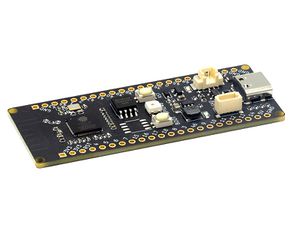
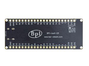
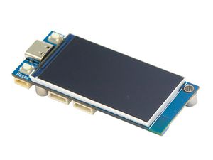
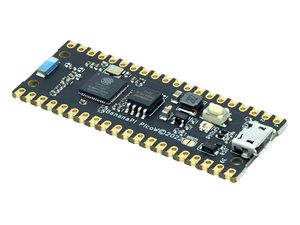
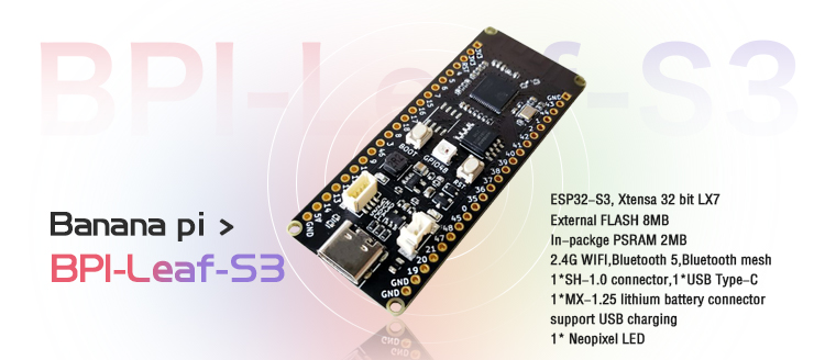
The Banana Pi BPI-Leaf-S3 is a series of low-powered microcontrollers designed for IoT development and Maker DIY board.It supports 2.4 GHz Wi-Fi and Bluetooth® LE dual-mode wireless communication, the peripheral is compatible with low-power hardware design, and the power consumption is only 10uA in deep sleep mode.
The main controller supports two power supply inputs: USB and external 3.7V lithium battery, both can be interchangable freely. The battery could also be charged while USB is plugged in. Compact size, various interface, easy to use, and can be directly applied to low-power IoT projects.
In terms of programming, the Leaf-S3 supports ESP-IDF, Arduino, micropython and other methods.
The IO pins on BPI-Leaf-S3 are identical to the Espressif ESP32-S3-DevKitC-1, developers can add peripherals that are supported by DevKitC-1 onto the BPI-Leaf-S3, and can also combine it onto a breadboard.
Key Features
- ESP32-S3,Xtensa® 32 bit LX7
- Extereal FLASH 8MB
- In-packge PSRAM 2MB
- Ultra-low power 10uA
- 2.4G WIFI ,Bluetooth 5 ,Bluetooth mesh
- GPIO , ADC , TOUCH , PWM , I2C , SPI , RMT , I2S , UART , LCD,CAMERA ,USB , JTAG
- 1* SH 1mm 4-Pin Socket, support I2C
- 1 * USB Type-C
- 1 * MX 1.25mm 2-Pin Socket,support USB charging
- 1 * Neopixel LED
ESP32-S3-DevKitC-1, BPI-Leaf-S3 Comparison
| Dev Board | BPI-Leaf-S3 | ESP32-S3-DevKitC-1 |
|---|---|---|
| GPIO Pins | 36 | 36 |
| 3.3v Pins | 3 | 3 |
| 5v Pins | 1 | 1 |
| GND Pins | 4 | 4 |
| ARGB LEDs | 1 on GPIO48 | 1 on GPIO48 |
| Chip Internal USB | USB-C Connector x 1 | MicroUSB Connector x 1 |
| UART TTL to USB | None | CP2102-MicroUSB Connector x 1 |
| External Battery Socket | 3.7v Li-ion Battery dock | None |
| Battery Charging | 500mA Charging Current | None |
| JST SH 1mm 4-Pin Socket | 1 | None |
The amount, numeric order, and spacing of IO pins on BPI-Leaf-S3 are identical to the Espressif ESP32-S3-DevKitC-1.
The BPI-Leaf-S3 dev board no longer equips traditional UART TTL to USB converter chip and its dedicated USB port. This is due to the ESP32-S3 chip's internal USB function were improved, supporting CDC-ACM virtual serial port and JTAG interface, which is capable of software development and firmware management feature, that makes the external converter chip redundant.
Compared to ESP32-S3-DevKitC-1 dev board, the BPI-Leaf-S3 adds an external battery socket and a charging circuit, capable of charging the battery via USB. When a 3.7v battery is connected, unplugging the USB will not cause the program to break, making it fit for multiple applications.
BPI-Leaf-S3 dev board is equipped with an I²C 4 pin dock, this stabalizes connection to other I²C peripherals. This dock is not only restricted to I²C connection, any module that requires a 3.3v pin, a GND pin, one or two data pin can also be connected to the Leaf-S3 via this 4 pin dock.
Espressif ESP32-S3
ESP32-S3 is a dual-core XTensa LX7 MCU, capable of running at 240 MHz. Apart from its 512 KB of internal SRAM, it also comes with integrated 2.4 GHz, 802.11 b/g/n Wi-Fi and Bluetooth 5 (LE) connectivity that provides long-range support. It has 45 programmable GPIOs and supports a rich set of peripherals. Compared with ESP32, it supports larger, high-speed octal SPI flash, and PSRAM with configurable data and instruction cache.
What follows is a description of the most important features of ESP32-S3.
- Wi-Fi + Bluetooth 5 (LE) Wireless Connectivity: ESP32-S3 supports a 2.4 GHz Wi-Fi (802.11 b/g/n) with 40 MHz of bandwidth support. The Bluetooth Low Energy subsystem supports long range through Coded PHY and advertisement extension. It also supports higher transmission speed and data throughput, with 2 Mbps PHY. Both Wi-Fi and BLE have superior RF performance that is maintained even at high temperatures.
- AI Acceleration Support: ESP32-S3 has additional support for vector instructions in the MCU, which provides acceleration for neural network computing and signal processing workloads. The software libraries for the above-mentioned optimized functions will become available very soon, in the form of updates to ESP-WHO and ESP-Skainet.
- Rich Set of IO Peripherals: ESP32-S3 has 44 programmable GPIOs, namely 10 more GPIOs than those of ESP32. ESP32-S3 supports all the commonly-used peripherals, such as SPI, I2S, I2C, PWM, RMT, ADC and UART, SD/MMC host and TWAITM. In total, 14 GPIOs can be configured as capacitive touch input for HMI applications. Apart from all these peripherals, however, ESP32-S3 is also equipped with an ultra-low-power (ULP) core that supports multiple low-power modes in a variety of such use-cases.
- Security:ESP32-S3 provides all the necessary security requirements for building securely connected devices, without requiring any external components. It supports AES-XTS-based flash encryption and RSA-based secure boot. In addition, ESP32-S3 has a digital signature peripheral and an HMAC module, which provide functionality that is similar to the hardware secure element, thus protecting the private or symmetric key from software attacks and identity theft. ESP32-S3 also has a “World Controller” peripheral that provides two fully-isolated execution environments, which enable the implementation of a trusted-execution environment or a privilege-separation scheme.
Getting Start
Hardware
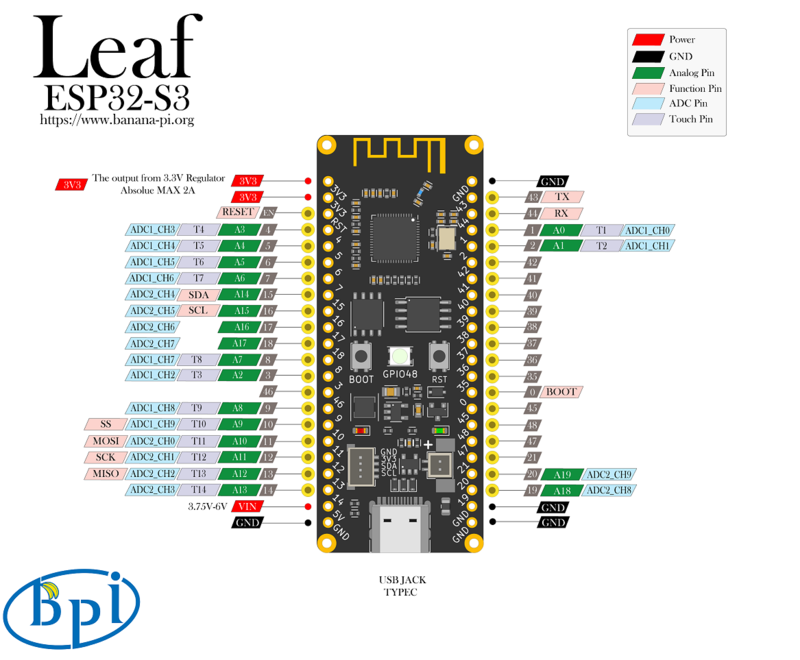
Hardware sketch map
Hardware Spec
| BPI-Leaf-S3 Spec | |
|---|---|
| SoC | ESP32-S3,Xtensa® dual-core 32-bit LX7 microprocessor |
| Clock Frequency | 240MHz MAX |
| Operating Temperature | -40℃~+85℃ |
| Internal ROM | 384 KB |
| Internal SRAM | 512 KB |
| Onboard FLASH ROM | 8MB |
| In-packge PSRAM | 2MB |
| WIFI | IEEE 802.11 b/g/n ,2.4Ghz,150Mbps |
| Bluetooth | Bluetooth 5 ,Bluetooth mesh |
| GPIO | BPI-Leaf-S3 has led out 36 available gpios |
| ADC | 2 × 12-bit SAR ADCs, up to 20 channels |
| Touch Sensor | 14 |
| SPI | 4 |
| I2C | 2 |
| I2S | 2 |
| LCD | 1 × LCD interface (8-bit ~16-bit parallel RGB, I8080 and MOTO6800) |
| CAMERA | 1 × DVP 8-bit ~16-bit camera interface |
| UART | 3 |
| PWM | 8 channels 14 bits |
| MCPWM | 2 |
| USB | 1 × full-speed USB OTG,female Type-C socket |
| USB Serial/JTAG controller | 1,CDC-ACM ,JTAG |
| Temperature Sensor | 1,ranging from -20 °C to 110 °C |
| SD/MMC | 1 × SDIO host controller with 2 slots,SD 3.0,SD 3.01,SDIO 3.0,CE-ATA 1.1,MMC 4.41,eMMC 4.5,eMMC 4.51 |
| TWAI® controller | 1 ,compatible with ISO 11898-1 (CAN Specification 2.0) |
| General DMA controller (GDMA) | 5 transmit channels and 5 receive channels |
| RMT | 4 TX channels,4RX channels.Eight channels share a 384 x 32-bit RAM |
| Pulse Count Controller | 4 independent pulse counters (units).Each unit consists of two independent channels |
| Timers | 4 × 54-bit general-purpose timers. 1 × 52-bit system timer. 3 × watchdog timers |
| External crystal oscillator | 40Mhz |
| RTC and LowPower Management | Power Management Unit (PMU) + Ultra-Low-Power Coprocessor(ULP) |
| Deep-sleep consumption current | 10uA |
| Operating Voltage | 3.3V |
| Input Voltage | 3.3V~5.5V |
| Maximum discharge current | [email protected] DC/DC |
| USB charge | Support |
| Maximum charging current | 500mA |
| Neopixel LED | 1 |
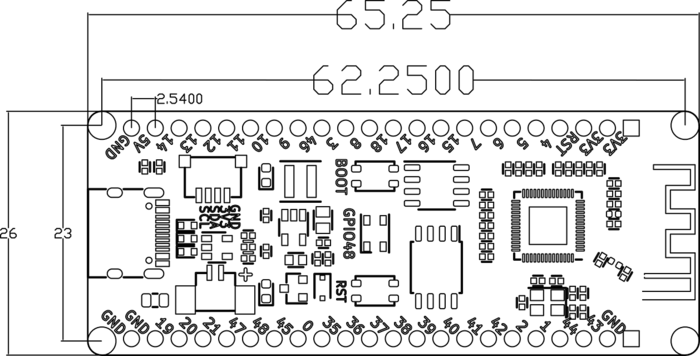
Hardware Dimensions
| BPI-Leaf-S3 Dimensions | |
|---|---|
| Pin spacing | 2.54mm |
| Mounting hole spacing | 23mm/ 62.25mm |
| Mounting hole size | bore 2mm/outside 3mm |
| Motherboard size | 26 × 65.25(mm)/1.02 x 2.57(inches) |
| board thickness | 1.2mm |
The pin spacing is breadboard compatible for easy application debugging.
Peripheral Pin Configurations
| BPI-Leaf-S3 GPIO Pin define | ||
|---|---|---|
| Peripheral Interface | Signal | Pin |
| ADC | ADC1_CH0~9 | GPIO 1~10 |
| ADC2_CH0~9 | GPIO 11~20 | |
| Touch sensor | TOUCH1~14 | GPIO 1~14 |
| JTAG | MTCK | GPIO 39 |
| MTDO | GPIO 40 | |
| MTDI | GPIO 41 | |
| MTMS | GPIO 42 | |
| UART | The pins are assigned by default, and can be redefined to any GPIO | |
| U0RXD_in | GPIO 44 | |
| U0CTS_in | GPIO 16 | |
| U0DSR_in | any GPIO | |
| U0TXD_out | GPIO43 | |
| U0RTS_out | GPIO 15 | |
| U0DTR_out | any GPIO | |
| U1RXD_in | GPIO 18 | |
| U1CTS_in | GPIO 20 | |
| U1DSR_in | any GPIO | |
| U1TXD_out | GPIO 17 | |
| U1RTS_out | GPIO 19 | |
| U1DTR_out | any GPIO | |
| U2 | any GPIO | |
| I2C | any GPIO | |
| PWM | any GPIO | |
| I2S | any GPIO | |
| LCD | any GPIO | |
| CAMERA | any GPIO | |
| RMT | any GPIO | |
| SPI0/1 | Used for FLASH and PSRAM | |
| SPI2/3 | any GPIO | |
| Pulse counter | any GPIO | |
| USB OTG | D- | GPIO 19(on-chip PHY) |
| D+ | GPIO 20(on-chip PHY) | |
| VP | GPIO 42(external PHY) | |
| VM | GPIO 41(external PHY) | |
| RCV | GPIO21(external PHY) | |
| OEN | GPIO 40(external PHY) | |
| VPO | GPIO 39(external PHY) | |
| VMO | GPIO38(external PHY) | |
| USB Serial/JTAG | D- | GPIO 19(on-chip PHY) |
| D+ | GPIO 20(on-chip PHY) | |
| VP | GPIO 42(external PHY) | |
| VM | GPIO 41(external PHY) | |
| OEN | GPIO 40(external PHY) | |
| VPO | GPIO 39(external PHY) | |
| VMO | GPIO38(external PHY) | |
| SD/MMC | any GPIO | |
| MCPWM | any GPIO | |
| TWAI | any GPIO | |
| Neopixel LED | GPIO 48 | |
Software
Espressif ESP-IDF
ESP-IDF is the development framework for Espressif SoCs supported on Windows, Linux and macOS.
It is recommend that developers install ESP-IDF via IDE.
- GitHub: ESP-IDF Eclipse Plugin README
- ESP-IDF VSCode Extension | GitHub: README | youtube: Quick User Guide for the ESP-IDF VSCode Extension
Or install manually based on operating system:
API:
To enable your BPI-Leaf-S3 device to flash via USB-CDC.
There are two ways to enter Bootloader mode:
- Connect it to the computer via USB, hold BOOT button, press RST button once, then release BOOT button.
- Hold BOOT button while disconnected to power, connect to PC via USB, then release BOOT button.
The chip controls GPIO0 via BOOT button to choose between reset or cold boot.
Confirm the port of your BPI-Leaf-S3 device via device manager, it might display different port if you are on different modes.
- ESP-DL (deep learning) Auto-Generating Model Deployment Project using TVM: https://docs.espressif.com/projects/esp-dl/en/latest/esp32/tutorials/deploying-models-through-tvm.html
MicroPython
Regardless of the programmer is a beginner or not, MicroPython is considered to be less difficult to develop than other MCU programming languages.
Its code is easy to understand compared to other programming languages, and it has various resources accumulated over the years by the open source community.
Just like Python, it has strong vitality and application value.
BPI-Steam resources
- MicroPython runtime environment setup
- Micropython firmware download and burning
- Basic use case
- ESP-NOW use case
Forum resources
- BPI-Leaf-S3 , ESP-NOW on MicroPython, easy to implement networking communication
- BPI-Leaf-S3 OLED displays potentiometer voltage and progress bar
- BPI-Leaf-S3 with ESP32-S3, use potentiometer to control neopixel steplessly
- BPI-Leaf-S3 with ESP32-S3, use key interrupts to control neopixel
- BPI-Leaf-S3 with ESP32-S3 & microPython Neopixel show
- BPI-Leaf-S3 microPython getting started, blink LED on bread board
- BPI-Leaf-S3+MicroPython: Display Web Clock on OLED screen
- BPI-Leaf-S3+MicroPython:Use ADC measuring potentiometer to control the motor
- Banana Pi BPI-Leaf-S3 MicroPython with TB6612FNG PWM Motor
- Making IoT programming easy,using MicroPython on BPI-Leaf-S3
CircuitPython
CircuitPython is a programming language designed to simplify experimenting and learning to code on low-cost microcontroller boards.
CircuitPython programming with Mu editor is the easiest way to get started. Install the software and connect the device to start using it.
BPI-Leaf-S3 CircuitPython Download Page
How to install tinyUF2 firmware:
To enable your BPI-Leaf-S3 device to flash via USB-CDC.
Connect it to the computer via USB, hold BOOT button, press RST button once, then release BOOT button.
In the Install, Repair, or Update UF2 Bootloader section at the bottom of the page, follow its instructions to download and install tinyUF2 firmware.
How to install CircuitPython firmware:
Click the DOWNLOAD .UF2 NOW button on the right side of the page to download the firmware to the local, and then copy it to the disk in BPI-Leaf-S3 UF2 Bootloader mode, and it can be used after automatic reset.
Supported by the adafruit/circuitpython GitHub repository
https://github.com/adafruit/circuitpython/pull/6904
Supported by the adafruit/tinyuf2 GitHub repository
https://github.com/adafruit/tinyuf2/pull/196
Arduino
Arduino is an open source embedded software and hardware development platform for users to create interactive embedded projects.
- Arduino IDE download link | Install and configure the Arduino-ESP32 runtime environment
- GitHub: BPI-Leaf-S3 Arduino Getting Started
- Arduino-ESP32 APIs
Supported by the arduino-esp32 GitHub repository
https://github.com/espressif/arduino-esp32/pull/7345
The board has been merged into the master branch.
Resources
Easy to buy sample
- BIPAI Aliexpress shop:https://www.aliexpress.com/item/1005004701866550.html?
- SINOVOIP Aliexpress shop : https://www.aliexpress.com/item/1005004428945296.html?spm=5261.ProductManageOnline.0.0.48af4edfYbyEoI
- Taobao shop : https://item.taobao.com/item.htm?spm=a2126o.success.0.0.29034831FGnLQW&id=677287234553
- OEM&OEM customized service : [email protected]
