Difference between revisions of "BPI-Bit"
(→Scratch) |
(→Resources) |
||
| Line 237: | Line 237: | ||
*How to Program Esp32 with Arduino IDE with C++ : https://technicalustad.com/program-esp32-with-arduino-ide-with-c/ | *How to Program Esp32 with Arduino IDE with C++ : https://technicalustad.com/program-esp32-with-arduino-ide-with-c/ | ||
*Banana Pi BPI:bit CE FCC RoHS Certification :http://forum.banana-pi.org/t/banana-pi-bpi-bit-ce-fcc-rohs-certification/7363 | *Banana Pi BPI:bit CE FCC RoHS Certification :http://forum.banana-pi.org/t/banana-pi-bpi-bit-ce-fcc-rohs-certification/7363 | ||
| + | *BPI:bit platformio official support :https://docs.platformio.org/en/latest/boards/espressif32/bpi-bit.html | ||
==Github== | ==Github== | ||
Revision as of 02:25, 17 April 2019
Introduction
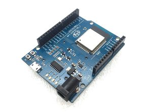
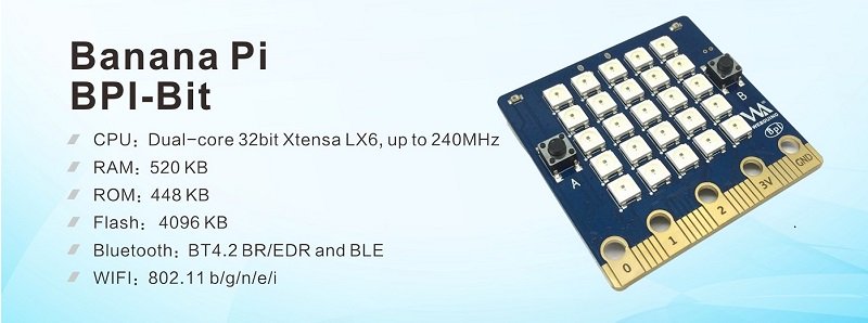
The BPI bit (also referred to as BPI-bit, stylised as bpi:bit) is an ESP32 with 32-bit Xtensa LX6 dual-core processor based embedded system. It supports Webduino, Arduino, MicroPython as well as Scratch X programming environments.
BPI:bit hardware main function:
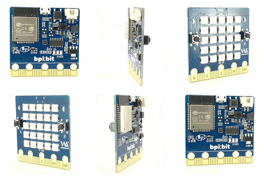
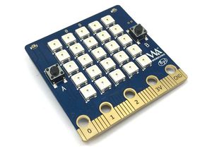
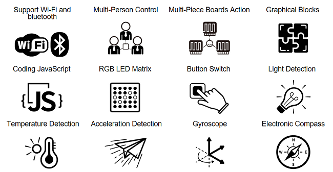
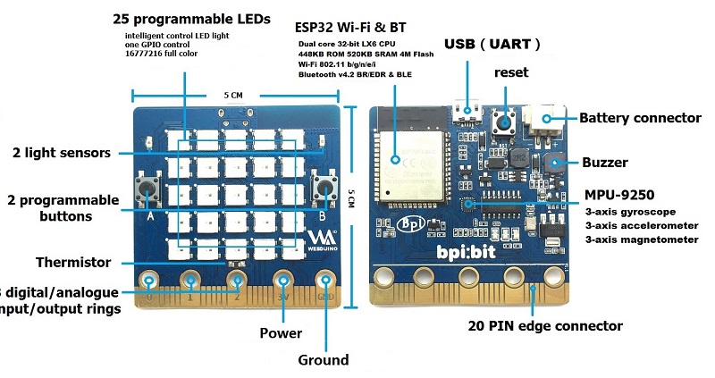
bpi:bit board is 5 cm x 5 cm in size, weighs 10 ~ 12 grams, it houses a 20-Pin edge connector, built-in lighting matrix with 25 programmable full-color LEDs , two photosensitive light sensors, two programmable buttons, an NTC resistor, a buzzer and a nine shaft sensor (triaxial acceleration Three-axis gyroscope and three-axis magnetic compass),
the I/O space configuration is as follows:
- Full color LED matrix: GPIO4
- Photosensitive sensor: GPIO36 (Analog A0, upper left), GPIO39 (Analog A3, upper right)
- Button switch : GPIO35 (Botton A), GPIO27 (Botton B)
- Temperature sensor: GPIO34 (Analog A6)
- Buzzer: GPIO25
- MPU-9250 9-axis sensor: GPIO0, GPIO21(SDA), GPIO22(SCL)
| GPIO control of BPI:bit | |||
| Light Sensor(L) | GPIO 36 | Analog Input | |
| Light Sensor(R) | GPIO 39 | Analog Input | |
| Botton A | GPIO 35 | Digital Input | |
| Botton B | GPIO 27 | Digital Input | |
| Temperature Sensor | GPIO 34 | Analog Input | |
| Buzzer | GPIO 25 | PWM(Digital Output) / Analog Output | |
| RGB_LED | GPIO 4 | Digital Output | |
| MPU9250_SCL | GPIO 22 | Digital Output | |
| MPU9250_SDA | GPIO 21 | Digital Output | |
| MPU9250_INT | GPIO 16 | Digital Input | |
| R_LED(SPI_SCK) | GPIO 18 | Digital Output | |
Hardware
Hardware description
Webduino Bit is the latest board of Webduino with much more sensors on top of its basic functions(Wi-Fi connection, muti-connectivity,multi-board...). It uses ESP32 module,one of the most efficient and stable chipset in the market, which has built-in 2.4G Wi-Fi and Bluetooth,448KB ROM,520KB SRAM,speed up to 600 DMIPS,and 40 nm technology.
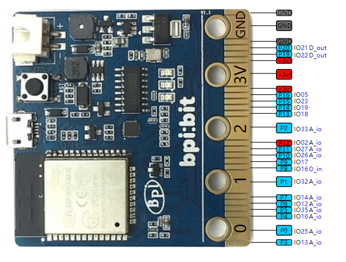
Webduion bit board has a compact size of 50mm x 50mm, weighs 10-12 grams.It has 20 pins at the bottom,25 full color LED array in the middle, two photo cells,two buttons, one thermistor,one buzzer,one 9-axis sensor(3-axis accelerometer,3-axis gyroscope and 3-axis magnetometer), the pin layout are below:
Hardware interface
PIN definitions
The edge interface is much compatible with those of micro:bit. so you may able to use micro:bit accessories on bpi:bit
| HardWare PIN define of BPI:bit | |||||
| Pin Name | Analog Function1 | Analog Function2 | Function1 | Function2 | Power |
| P3 | ADC2_CH4 | GPIO13 | |||
| P0 | ADC2_CH8 | DAC_1 | GPIO25 | ||
| P4 | ADC2_CH3 | GPIO16 | |||
| P5 | ADC1_CH7 | GPIO35 | |||
| P6 | ADC2_CH5 | GPIO12 | |||
| P7 | ADC2_CH6 | GPIO14 | |||
| P1 | ADC1_CH4 | GPIO32 | |||
| P8 | GPIO16 | ||||
| P9 | GPIO17 | ||||
| P10 | ADC2_CH9 | DAC_2 | GPIO26 | ||
| P11 | ADC2_CH7 | GPIO27 | |||
| P12 | ADC2_CH2 | GPIO02 | |||
| P2 | ADC1_CH5 | GPIO33 | |||
| P13 | GPIO18 | SPI_SS | |||
| P14 | GPIO19 | SPI_SCK | |||
| P15 | GPIO23 | SPI_MISO | |||
| P16 | GPIO05 | SPI_MOSI | |||
| 3V3 | POWER:3V3 | ||||
| 3V3 | POWER:3V3 | ||||
| 3V3 | POWER:3V3 | ||||
| P19 | GPIO22 | I2C_SCL | |||
| P20 | GPIO21 | I2C_SDA | |||
| GND | GROUND | ||||
| GND | GROUND | ||||
| GND | GROUND | ||||
5*5 25 LED
BPI:bit have 25 LEDs on board, it can be controlled with a single GPIO.
| 25 5*5 LED list of BPI:bit | ||||
| 20 | 15 | 10 | 5 | 0 |
| 21 | 16 | 11 | 6 | 1 |
| 22 | 17 | 12 | 7 | 2 |
| 23 | 18 | 13 | 8 | 3 |
| 24 | 19 | 14 | 9 | 4 |
MPU9250 9-axis sensor
The 9-axis sensor, MPU9250, is placed on the BPI:bit board. and MPU9250 uses I2C 0x69 address.
The 9-axis is the combination of 3 separate triple axis sensors. For more detailed information of this chip, click here MPU 9250 datasheet to view the datasheet.\
BPI-BIT MPU9250 Library and how to : https://github.com/BPI-STEAM/MPU9250
BPI:bit power
When you use BPI:bit, you need to supply the board first, and the bit supports three power supply modes
- 1.micro USB port:USB cable power supply, the design of BPI:bit board has Micro USB interface, which is quite common in daily life and is quite convenient to use.
- 2.Battery port:Through 2 pin battery power supply socket, can through the lithium battery, battery pack to power supply board, interface fool proof design, don't worry about the power supply through the 2 pin battery power supply socket, can through the lithium battery, battery pack to power supply board, interface fool proof design, don't have to worry about power supply meet the problem.
- 3.Goldfinger :Power is supplied through the gold finger, and the gold finger at the bottom of the board contains the power interface. Meanwhile, it has both input and output functions and has high compatibility.
BPI:bit VS micro:bit
| bpi:bit VS micro:bit | |||||||
| Module | bpi:bit | micro:bit | |||||
| CPU | Dual-core 32bit Xtensa LX6, up to 240MHz | NXP KL26Z 32bit ARM Cortex M0, up to 16MHz | |||||
| RAM | 520 KB | 16 KB | |||||
| ROM | 448 KB | Unkown | |||||
| Flash | 4096 KB | 256 KB | |||||
| Bluetooth | BT4.2 BR/EDR and BLE | BLE only | |||||
| WIFI | 802.11 b/g/n/e/i | N/A | |||||
| Buzzer | 1x Buzzer | N/A | |||||
| 5*5 LEDS | 25 intelligent-control full-color (16777216 color) LEDs, Cascading all LEDs by a single line. | 25 red LEDs | |||||
| photosensitive sensor | 2 light sensors | Basic light detection function on LEDs | |||||
| temperature sensor | Stand along temperature sensor | On CPU chip temperature sensor | |||||
| Motion sensor | MPU-9250 9-axis Motion Tracking : 3-axis accelerometer, 3-axis magnetometer, 3-axis gyroscope | 3-axis Accelerometer; 3-axis magnetometer; no gyroscope, no motion processor | |||||
| IO interface | edge interface (compatible with most micro:bit I/O features) | edge interface | |||||
| Button | 2 programmable buttons | 2 programmable buttons | |||||
| micro USB | 1x micro USB(UART) | 1 x micro USB(Mass Storage Device) | |||||
| Software | Webduino, Arduino, MicroPython, Scratch X | Microsoft MakeCode, MicroPython, Scratch X | |||||
| Size | 5*5 cm | 5*4 cm | |||||
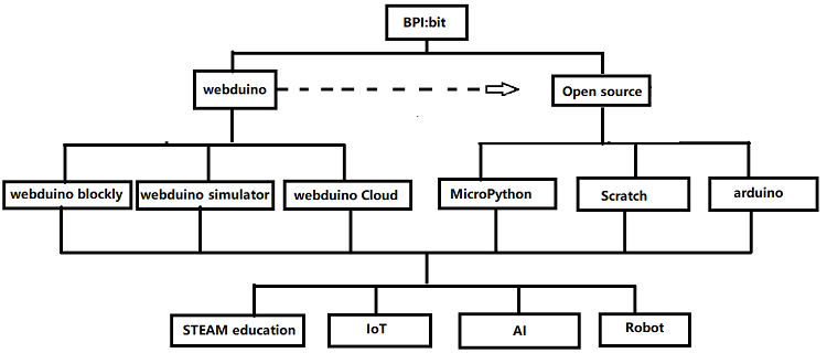
BPI:bit Software development
BPI:bit Software development schedule and support applications:
BPI:bit for Webduino
BPI:bit for Arduino
BPI:bit for MicroPyhton
BPI:bit for Scratch
Resources
- BPI:bit user manual
- BPI:bit V1.4 schematic diagram
- BPI:bit V1.2 schematic diagram
- BPI:bit dxf file
- BPI:bit Webduino Easy How-To's Episode 1: Initial Setup : https://www.youtube.com/watch?v=23_a27N3_7k
- How to Program Esp32 with Arduino IDE with C++ : https://technicalustad.com/program-esp32-with-arduino-ide-with-c/
- Banana Pi BPI:bit CE FCC RoHS Certification :http://forum.banana-pi.org/t/banana-pi-bpi-bit-ce-fcc-rohs-certification/7363
- BPI:bit platformio official support :https://docs.platformio.org/en/latest/boards/espressif32/bpi-bit.html
