Difference between revisions of "UniPi on BPI"
(→about UniPi) |
|||
| (One intermediate revision by the same user not shown) | |||
| Line 1: | Line 1: | ||
| − | + | =about UniPi= | |
| − | UniPi | ||
| − | + | [[File:UniPi-11-otl.jpg|thumb|Overview]] | |
| − | |||
| − | |||
UniPi board is designed to fit the cheap and easy to use Raspberry Pi mini computer. It has 8 changeover relays, 14 digital inputs, single channel 1wire interface, 2 analog inputs 0-10V and one analog 0-10V output. Furthermore the second I2C port of the RPi features 5V level converter and ESD protection, so you can easily connect other devices. The same applies to the UART! | UniPi board is designed to fit the cheap and easy to use Raspberry Pi mini computer. It has 8 changeover relays, 14 digital inputs, single channel 1wire interface, 2 analog inputs 0-10V and one analog 0-10V output. Furthermore the second I2C port of the RPi features 5V level converter and ESD protection, so you can easily connect other devices. The same applies to the UART! | ||
| Line 10: | Line 7: | ||
Does it have anything else that might be usable? Of course! It has Real Time Clock module so if your Pi looses power, the clock stays synced so when the system comes up, it will do everything as planned. | Does it have anything else that might be usable? Of course! It has Real Time Clock module so if your Pi looses power, the clock stays synced so when the system comes up, it will do everything as planned. | ||
| − | + | [[File:Unpi_1.jpg]] | |
*more about UniPi: | *more about UniPi: | ||
| Line 23: | Line 20: | ||
Version: 1.0 HDMI | Version: 1.0 HDMI | ||
| − | + | [[File:Unpi_2.jpg]] | |
Step 1: Download WiringPI | Step 1: Download WiringPI | ||
Latest revision as of 19:54, 16 May 2018
about UniPi
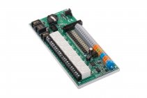
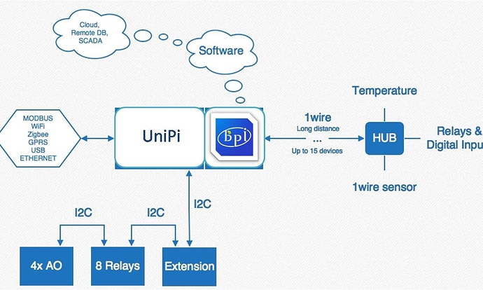
UniPi board is designed to fit the cheap and easy to use Raspberry Pi mini computer. It has 8 changeover relays, 14 digital inputs, single channel 1wire interface, 2 analog inputs 0-10V and one analog 0-10V output. Furthermore the second I2C port of the RPi features 5V level converter and ESD protection, so you can easily connect other devices. The same applies to the UART!
Does it have anything else that might be usable? Of course! It has Real Time Clock module so if your Pi looses power, the clock stays synced so when the system comes up, it will do everything as planned.
- more about UniPi:
- UniPi Introduction: http://unipi.technology/
How to use UniPi on banana pi
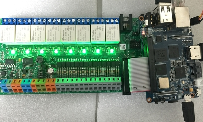
we test it on BPI-M3 with WiringPi lib. so other BPI board is same as BPI-M3
OS: BPI-M3 Ubuntu15.10 (Kernel3.4)
Version: 1.0 HDMI
Step 1: Download WiringPI
$ git clone https://github.com/BPI-SINOVOIP/BPI-WiringPi.git11 -b BPI_M3
$ cd BPI-WiringPi
$ chmod +x ./build
$ sudo ./build
Step 2:Check the 8Relays(MCP23008)
device to see if it's on track.(address 0x20)
(I2c port number for M3: 2 )
sudo su
i2cdetect -y 2
.0 1 2 3 4 5 6 7 8 9 a b c d e f
00: -- -- -- -- -- -- -- -- -- -- -- -- --
10: -- -- -- -- -- -- -- -- 18 -- -- -- -- -- -- --
20: 20 -- -- -- -- -- -- -- -- -- -- -- -- -- -- --
30: -- -- -- -- -- -- -- -- -- -- -- -- -- -- -- --
40: -- -- -- -- -- -- -- -- -- -- -- -- -- -- -- --
50: 50 -- -- -- -- -- -- 57 -- -- -- -- -- -- -- --
60: -- -- -- -- -- -- -- -- 68 -- -- -- -- -- -- 6f
70: -- -- -- -- -- -- -- --
Step 3 : Copy smaple code to mcp23008.c file
$ sudo vi mcp23008.c
Step 4 : Compile mcp23008.c
$ gcc -o mcp23008 mcp23008.c -l wiringPi
Step 5: Run mcp23008
$ sudo ./mcp23008
- Vedeo demo on youtube : https://www.youtube.com/watch?v=-4dgZZLFl3g&feature=youtu.be
Sample Code
#include <stdio.h>
#include <wiringPi.h>
#include <mcp23008.h>
#define PIN_BASE 65
#define ADDRESS 0x20
int main(int argc, char *argv[])
{
 int s;
 int count=65;
 wiringPiSetup();
 mcp23008Setup(PIN_BASE, ADDRESS);
 for(int i=0 ; i<8 ;i++){
  pinMode(count , OUTPUT);
  count=(count+1);
  }
 while(1){
   s = digitalRead(PIN_BASE);
   printf("Status switch is %d\n", s);
   count=PIN_BASE;
   for(int i=0 ; i<8 ;i++){
     digitalWrite(count , 1);
     count=count+1;
   }
   delay(1000);
   s = digitalRead(PIN_BASE);
   printf("Status switch is %d\n", s);
   count=PIN_BASE;
   for(int i=0 ; i<8 ;i++){
     digitalWrite(count , 0);
     count=count+1;
   }
   delay(1000);
}
 return 0;
}
link to forum for discuss:
http://forum.banana-pi.org/t/bpi-m3-use-the-unipi-8relays-mcp23008-module-demo/1121


