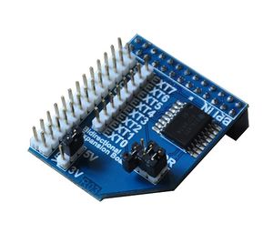
BPI I2C GPIO extend module
Contents
Product Overview
This module is designed specifically for expand for the GPIO of the Banana Pi a which can effectively solve the banana send IO port insufficient. It use PCF8574 chip to expand 8 Bidirectional IO. The module connection to the Banana Pi through I2C bus. There are 8 I2C address in the module and user can choose one of them through setup the “ADDR” jumper. User also can choose 5V or 3.3V electric level. Module with isolation protection, can effectively prevent external high voltage damage to the Banana Pi. Multiple module can cascade.
Product Features
- 1. 8 Bidirectional IO
- 2. 8 I2C-address
- 3. Isolation protection
- 4. Use wiringPi API , sample code
- 5. 100 kHz I2C-bus interface (Standard-mode I2C-bus)
Typical Application
- 1. LED signs and displays
- 2. Key pads
- 3. Instrumentation and test measurement
- 4. Driver numeric display
- 5. Drive the lattice screen
Product Parameters
- 1. Working voltage: 2.5V-6V
- 2. IO voltage: 3.3V or 5.5
- 3. Expand 8 Bidirectional IO
- 4. I2C bus
- 5. 100 kHz I2C-bus interface (Standard-mode I2C-bus)
- 6. −40°C to +85°C operation
Hardware
Product Specification
Schematic diagram
Port
- 1. Banana Pi insert port
- 2. Banana Pi cascade port
- 3. EXT0-EXT7 expand GPIO
- 4. Electric level selection jumper
- 5. I2C-address selection jumper
More Information
Insert the module that the silk screen says “BPI IN”. Pay attention don’t make the direction reversed! The correct direction of insert module is above the Banana Pi’s PCB; EXT0-EXT7 are expand GPIO,user can use DuPont Line to connection peripheral. The header which near silk screen write ”EXT” expand GPIO of Banana Pi, user can cascade the other module or the same module. If you want switch the electric level, just setup the jumper
The PCF8574/74A provides general-purpose remote I/O expansion via the two-wire bidirectional I2C-bus (serial clock (SCL), serial data (SDA)).
The devices consist of eight quasi-bidirectional ports, 100 kHz I2C-bus interface, three hardware address inputs and interrupt output operating between 2.5 V and 6 V. The quasi-bidirectional port can be independently assigned as an input to monitor interrupt status or keypads, or as an output to activate indicator devices such as LEDs. System master can read from the input port or write to the output port through a single register.
The low current consumption of 2.5uA (typical, static) is great for mobile applications and the latched output ports directly drive LEDs.
The PCF8574 and PCF8574A are identical, except for the different fixed portion of the slave address. The three hardware address pins allow eight of each device to be on the same I2C-bus, so there can be up to 16 of these I/O expanders PCF8574/74A together on the same I2C-bus, supporting up to 128 I/Os (for example, 128 LEDs).
The active LOW open-drain interrupt output (INT) can be connected to the interrupt logic of the microcontroller and is activated when any input state differs from its corresponding input port register state. It is used to indicateto the microcontroller that an input state has changed and the device needs to be interrogated without the microcontroller continuously polling the input register via the I2C-bus. The internal Power-On Reset (POR) initializesthe I/Os as inputs with a weak internal pull-up 100uA current source.
Address Table:
Timing Diagram:
Testbench:
- 1. Use: sudo i2cdetect –y –a 1check the I2C-address
- 2. Use wiringPi API, initialize module
- 3. Setup IO to OUTPUT mode, 5V high level and check the level of the state with a multimeter
- 4. Setup IO to OUTPUT mode, 3V high level and check the level of the state with a multimeter
- 5. Setup IO to INPUT mode, input 5V high level and check the IO status through wiringPi
- 6. Setup IO to INPUT mode, input 3V high level and check the IO status through wiringPi
- 7. Finish test
- More information please check:**
http://www.nxp.com/products/interface_and_connectivity/i2c/i2c_general_purpose_i_o/PCF8574T.html
How to use
How to use I2C module on BPI-M3
OS: BPI-M3 Ubuntu15.10 (Kernel3.4)
Version: 1.0 HDMI
Step 1: Download WiringPI
$ git clone https://github.com/BPI-SINOVOIP/BPI-WiringPi.git1111 -b BPI_M3
$ cd BPI-WiringPi
$ chmod +x ./build
$ sudo ./build```
Step 2:Check the BPI I2C GPIO extend(PCF8574) device to see if it's on track.(address 0x27) (I2c port number for M3: 2 )
sudo su
i2cdetect -y 2
.0 1 2 3 4 5 6 7 8 9 a b c d e f
00: -- -- -- -- -- -- -- -- -- -- -- -- --
10: -- -- -- -- -- -- -- -- -- -- -- -- -- -- -- --
20: -- -- -- -- -- -- -- 27 -- -- -- -- -- -- -- --
30: -- -- -- -- -- -- -- -- -- -- -- -- -- -- -- --
40: -- -- -- -- -- -- -- -- -- -- -- -- -- -- -- --
50: -- -- -- -- -- -- -- -- -- -- -- -- -- -- -- --
60: -- -- -- -- -- -- -- -- -- -- -- -- -- -- -- --
70: -- -- -- -- -- -- -- --```
Step 3 : Copy smaple code to i2c_pcf8574.c file
$ sudo vi i2c_pcf8574.c
Step 4 : Compile i2c_pcf8574.c
$ gcc -o i2c_pcf8574 i2c_pcf8574.c -l wiringPi
Step 5: Run i2c_pcf8574
$ sudo ./i2c_pcf8574
Video Demo on youtube:
https://www.youtube.com/watch?v=3zmB9jTaJds&feature=youtu.be
Sample Code:
#include <wiringPi.h>
#include <pcf8574.h>
#include <stdio.h>
int main()
{
int i;
pcf8574Setup(100,0x27);
for(i=0;i<8;i++) pinMode(100+i,OUTPUT);
while(1)
{
i = 0;
for(i=0;i<=8;i++)
{
printf("Current LED = %d\n",100+i);
digitalWrite((100+i),HIGH);
delay(500);
digitalWrite((100+i),0);
delay(500);
}
}
}
