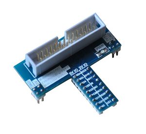
BPI GPIO extend module T type
Contents
Product Overview
This module is designed specifically for convert the GPIO electric level of Banana Pi. It can convert 3.3V electric level to 5.5V electric level. That makes the Banana Pi compatible 5V peripheral. Modules are drawn twice a 5V Vcc and 3.3V Vcc; module IO are all below the left side of the 5V level IO, the right of all to 3V level IO. It is connected via cable 2 * 13 and banana pie GPIO port, and then plug in the breadboard module can be used.
Produce Feature
- 1. Convert 3.3V GPIO to 5V GPIO
- 2. 3.3V GPIO and 5V FPIO classification
- 3. Can be used in breadboard
- 4. Use TI TXB0108 chip
Port
- 1. 5V Vcc
- 2. 3.3V Vcc
- 3. 5V GPIO
- 4. 3V GPIO
- 5. Banana Pi connect port,also can use on raspberry pi.
Product Parameters
- 1. Working voltage: 1.65V-5.5V
- 2. Drive current up to 50mA
- 3. Low Power Consumption, 4-μA Max Icc
- 4. −40°C to +85°C operation
Typical Application
- 1. Convert electric level
- 2. Breadboard test
- 3. DIY hands-on experiments
Product Specification
Error creating thumbnail: Unable to save thumbnail to destination
Error creating thumbnail: Unable to save thumbnail to destination
Schematic diagram
Error creating thumbnail: Unable to save thumbnail to destination
How to use on BPI-M3
OS: BPI-M3 Ubuntu15.10 (Kernel3.4)
Version: 1.0 HDMI
Error creating thumbnail: Unable to save thumbnail to destination
Step 1: Download WiringPI
$ git clone https://github.com/BPI-SINOVOIP/BPI-WiringPi.git111 -b BPI_M3
$ cd BPI-WiringPi
$ chmod +x ./build
$ sudo ./build```
Step 2 : Copy smaple code to led.c file
$ sudo vi led.c
Step 3 : Compile led.c
$ gcc -o led led.c -l wiringPi
Step 4: Run led
$ sudo ./led
Sample Code:
#include <stdio.h>
#include <wiringPi.h>
#define	LED_1 8 //BPI SDA
#define	LED_2 11 //BPI CE1
#define	LED_3 0 //BPI GPIO0
int main (void)
{
int i;
printf ("BPI-M3 blink\n") ;
//wiringPiSetupPhys() ; //phy
//wiringPiSetupGpio(); //bcm
wiringPiSetup(); //wiringPi
pinMode (LED_1, OUTPUT) ;
pinMode (LED_2, OUTPUT) ;
pinMode (LED_3, OUTPUT) ;
for (;;)
{
digitalWrite (LED_1, HIGH) ;	// On
digitalWrite (LED_2, HIGH) ;
digitalWrite (LED_3, HIGH) ;
delay (500) ;	// mS
digitalWrite (LED_1, LOW) ;	// Off
digitalWrite (LED_2, LOW) ;
digitalWrite (LED_3, LOW) ;
delay (500) ;
}
return 0 ;
}
- More information please check : http://www.ti.com.cn/product/cn/TXB0108/description?keyMatch=txb0108pwr&tisearch=Search-CN
Testbench
- 1. Connect the module to Banana Pi
- 2. Set all of the GPIO of Banana Pi to OUTPUT mode;
- 3. Set all of GPIO to High level, find the voltage is 5V or 3.3V
- 4. Set all of GPIO to Low level, find the voltage near 0V.;
- 5. Finish test
