Difference between revisions of "Getting Started with BPI-R3 MINI"
(→Network-Configuration) |
(→Network-Configuration) |
||
| Line 64: | Line 64: | ||
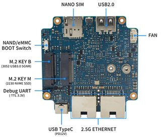
*Network Interface: eth1 is for WAN; eth0, rax0, ra0 is for LAN, ra0 is for 2.4G wireless, rax0 is for 5G wireless. | *Network Interface: eth1 is for WAN; eth0, rax0, ra0 is for LAN, ra0 is for 2.4G wireless, rax0 is for 5G wireless. | ||
| − | [[ | + | [[File:BPI-R3_MINI_interface.jpg|640px]] |
root@OpenWrt:/# ifconfig | root@OpenWrt:/# ifconfig | ||
Revision as of 03:01, 26 July 2023
Contents
Introduction
Banana Pi BPI-R3 Mini Router board with MediaTek MT7986(Filogic 830) quad core ARM A53 chip design ,2G DDR RAM ,8G eMMC flash onboard,It is a very high performance open source router development board,support Wi-Fi6 2.4G wifi use MT7976 and 5G wifi use MT7976, support 2 2.5GbE network port.
MediaTek MT7986(Filogic 830)
The MT7986(Filogic 830) integrates four Arm Cortex-A53 cores up to 2GHz with up to 18,000 DMIPs of processing power and 6Gbps of dual 4x4 Wi-Fi6 connectivity. It has two 2.5g Ethernet interfaces and serial peripheral interfaces (SPI). Filogic 830‘s built-in hardware acceleration engine enables fast and reliable Wi-Fi offloading and wireless network connection. In addition, the chip supports Mediatek FastPath™ technology, which is suitable for games, AR/VR and other low-latency applications.
Wi-fi 6 has many advantages over its predecessors, including lower latency, larger bandwidth capacity and faster transmission rates. Wireless network devices supporting the 6GHz band mainly use 160MHz wide channel and 6GHz uncongested bandwidth to provide multigigabit transmission and low-latency wi-fi connection, providing reliable wireless network for streaming media, games, AR/VR and other applications.
Key Features
- MediaTek MT7986(Filogic 830) Quad core ARM Cortex A53
- Wifi 6 2.4G/5G(MT7976C)
- 2G DDR RAM
- 8G eMMC flash
- 128MB Nand flash
- 2x 2.5GbE network port
- 1x M.2 Key B USB inerface
- 1x M.2 KEY M PCIe inerface
- 1x USB2.0 interface
Development
Basic Development
Prepare to develop
 * Prepare USB-Serial interface
 * Using your USB-Serial Connect debug console on BPI-R3 MINI
  Note: Debug Uart 3.3v TTL

 *R3 boot switch Jumper Setting
  Note: EMMC Boot or Nand boot Support.
Warnning
 Note: Because BPI-R3 MINI can't support that it boot from SD, So the factory will flash one default image into Nand and EMMC Device. if you want to update EMMC device, please boot from Nand, otherwise you update Nand device when it boot from EMMC.
 Anytime please confirm that one EMMC or Nand device include one bootable image, it's very important.
How to burn image to onboard eMMC
Note: when you want to Update EMMC device, Firstly Change boot switch to boot from Nand device, then after boot up,you need flash one emmc image into EMMC device. Finally you change bootstrap to boot from EMMC.
Before burning image to eMMC, please prepare a USB disk. Let's take OpenWrt image (mtk-bpi-r3mini-EMMC-20230719.img, bl2_emmc.img) for example, the steps are below:
 1. Copy EMMC boot OpenWrt image(mtk-bpi-r3mini-EMMC-20230719.img, bl2_emmc.img) to USB disk.

 2. Change boot switch Jumper, the board boot from Nand device, then power up the board.

 3. Plug in USB disk to the board, and mount the USB to /mnt or other directory as follows: (you can skip mounting if it is mounted automatically)
    * mount -t vfat /dev/sda1 /mnt
    * change your directory to the mounting point, here is : cd /mnt
 4. Execute following command to enable and copy image to EMMC device:
    * echo 0 > /sys/block/mmcblk0boot0/force_ro
    * dd if=bl2_emmc.img of=/dev/mmcblk0boot0
    * dd if=mtk-bpi-r3mini-EMMC-20230719.img of=/dev/mmcblk0
    * mmc bootpart enable 1 1 /dev/mmcblk0
 7. power off R3MINI board, remove u-disk driver, change bootstrap to boot from emmc device.
    Note: Enable EMMC device, boot strap is from EMMC.
Network-Configuration
- Network-Configuration refer to: http://www.fw-web.de/dokuwiki/doku.php?id=en:bpi-r2:network:start
- Network Interface: eth1 is for WAN; eth0, rax0, ra0 is for LAN, ra0 is for 2.4G wireless, rax0 is for 5G wireless.

root@OpenWrt:/# ifconfig
br-lan Link encap:Ethernet HWaddr EE:A1:57:81:CA:19
         inet addr:192.168.1.1  Bcast:192.168.1.255  Mask:255.255.255.0
         inet6 addr: fe80::eca1:57ff:fe81:ca19/64 Scope:Link
         inet6 addr: fd63:8bea:d5ce::1/60 Scope:Global
         UP BROADCAST RUNNING MULTICAST  MTU:1500  Metric:1
         RX packets:0 errors:0 dropped:0 overruns:0 frame:0
         TX packets:15 errors:0 dropped:0 overruns:0 carrier:0
         collisions:0 txqueuelen:1000
         RX bytes:0 (0.0 B)  TX bytes:2418 (2.3 KiB)
br-wan Link encap:Ethernet HWaddr EE:A1:57:81:CA:19
         inet6 addr: fe80::eca1:57ff:fe81:ca19/64 Scope:Link
         UP BROADCAST RUNNING MULTICAST  MTU:1500  Metric:1
         RX packets:0 errors:0 dropped:0 overruns:0 frame:0
         TX packets:34 errors:0 dropped:0 overruns:0 carrier:0
         collisions:0 txqueuelen:1000
         RX bytes:0 (0.0 B)  TX bytes:8538 (8.3 KiB)
eth0 Link encap:Ethernet HWaddr EE:A1:57:81:CA:19
         inet6 addr: fe80::eca1:57ff:fe81:ca19/64 Scope:Link
         UP BROADCAST RUNNING MULTICAST  MTU:1500  Metric:1
         RX packets:0 errors:0 dropped:0 overruns:0 frame:0
         TX packets:32 errors:0 dropped:0 overruns:0 carrier:0
         collisions:0 txqueuelen:1000
         RX bytes:0 (0.0 B)  TX bytes:4408 (4.3 KiB)
         Interrupt:124
eth1 Link encap:Ethernet HWaddr 4A:BB:84:B4:5D:3F
         UP BROADCAST RUNNING MULTICAST  MTU:1500  Metric:1
         RX packets:0 errors:0 dropped:0 overruns:0 frame:0
         TX packets:34 errors:0 dropped:0 overruns:0 carrier:0
         collisions:0 txqueuelen:1000
         RX bytes:0 (0.0 B)  TX bytes:8674 (8.4 KiB)
         Interrupt:124
lo Link encap:Local Loopback
         inet addr:127.0.0.1  Mask:255.0.0.0
         inet6 addr: ::1/128 Scope:Host
         UP LOOPBACK RUNNING  MTU:65536  Metric:1
         RX packets:56 errors:0 dropped:0 overruns:0 frame:0
         TX packets:56 errors:0 dropped:0 overruns:0 carrier:0
         collisions:0 txqueuelen:1000
         RX bytes:4368 (4.2 KiB)  TX bytes:4368 (4.2 KiB)
ra0 Link encap:Ethernet HWaddr 00:0C:43:26:60:38
         UP BROADCAST RUNNING MULTICAST  MTU:1500  Metric:1
         RX packets:0 errors:0 dropped:0 overruns:0 frame:0
         TX packets:0 errors:0 dropped:0 overruns:0 carrier:0
         collisions:0 txqueuelen:1000
         RX bytes:0 (0.0 B)  TX bytes:0 (0.0 B)
         Interrupt:6
rax0 Link encap:Ethernet HWaddr 02:0C:43:36:60:38
         UP BROADCAST RUNNING MULTICAST  MTU:1500  Metric:1
         RX packets:0 errors:0 dropped:0 overruns:0 frame:0
         TX packets:0 errors:0 dropped:0 overruns:0 carrier:0
         collisions:0 txqueuelen:1000
         RX bytes:0 (0.0 B)  TX bytes:0 (0.0 B)
root@OpenWrt:/# brctl show br-wan
bridge name bridge id STP enabled interfaces br-wan 7fff.eea15781ca19 no lan0, eth1
root@OpenWrt:/# brctl show br-lan
bridge name bridge id STP enabled interfaces br-lan 7fff.eea15781ca19 no lan4, rax0, lan2, lan5, ra0, lan3, lan1
root@OpenWrt:/#
Advanced Development
GPIO Control
- echo xxx > /sys/class/gpio/export
- echo in/out > /sys/class/gpio/gpioxxx/direction
- echo 0/1 > /sys/class/gpio/gpioxxx/value
Check the base gpio, you could see mine is 411

For example: if you want to change gpio 22 as out highlevel, you need input commands like this:
- echo 433(22+411) > /sys/class/gpio/export
- echo out > /sys/class/gpio/gpio433/direction
- echo 1 > /sys/class/gpio/gpio433/value
FAN

- R317 for 5V FAN and R318 for 12V FAN.
- CN23 supports PWM control while CN22 does not support.
PWM FAN Control
- echo 0 > /sys/class/pwm/pwmchip0/export
- echo 10000 > /sys/class/pwm/pwmchip0/pwm0/period
- echo 5000 > /sys/class/pwm/pwmchip0/pwm0/duty_cycle
- echo normal > /sys/class/pwm/pwmchip0/pwm0/polarity
- echo 1 > /sys/class/pwm/pwmchip0/pwm0/enable
miniPCIe slot
currently, miniPCIe slot only support one USB 4G module, example: EC25 when you insert one EC25 module, you may check it.

SFP
After high and low temperature test, the following modules are suppoted by BPI-R3:

4G&5G
- BPI-R3 supports 4G LTE EC25.
- If you want to use 5G on BPI-R3:
   1. Insert 5G dongle into USB3.0.
   2. Connect RG200U-CN to mini PCIe, connect SoC through USB2.0(speed limited).
   3. Make an RG200U-CN LGA adapter board and insert it into M.2 KEY M.
Note: The availability of 4G/5G depends on the local carrier frequency band.
Ap mode on BPI-R3
- ra0 is MT7986a 2.4G wifi
- rax0 is MT7986a 5G wifi
Wifi & Serial cable
- If the chip type of serial cable is pl2303, the driver fails to load the firmware apparently and thus the wifi can't work.
- Other types including cp2102,ch340 and FDTI are all available, serial cable vlotage must be 3.3v LVTTL standard.
UART_TX0 is the Boot Strapping PIN and must be kept low during power-on.

FAQ
- MT7986a Reference Manual for Develope Board(BPi)
TTL Voltage
- The debug-uart TTL is tolerant to 3.3V.