Difference between revisions of "Getting Started with M5/M2Pro"
(→Android) |
(→Install Docker Engine) |
||
| (192 intermediate revisions by 2 users not shown) | |||
| Line 1: | Line 1: | ||
=Introduction= | =Introduction= | ||
[[File:Banana_Pi_BPI-M5_4.JPG|thumb|[[Banana Pi BPI-M5]]]] | [[File:Banana_Pi_BPI-M5_4.JPG|thumb|[[Banana Pi BPI-M5]]]] | ||
| + | [[File:BPI-M2_Pro_2.jpg|thumb|[[Banana Pi BPI-M2 Pro]] S905x3 design]] | ||
[[File:Banana_Pi_BPI-M5_1.JPG|thumb|Amlogic S905X3 Processor]] | [[File:Banana_Pi_BPI-M5_1.JPG|thumb|Amlogic S905X3 Processor]] | ||
| Line 25: | Line 26: | ||
==Prepare== | ==Prepare== | ||
| − | :1. Prepare a usb-serial cable, a 5V/ | + | :1. Prepare a usb-serial cable, a 5V/3A adaptor type-c power supply. The serial cable is used for console debug and type-c cable is used for android image download and ADB debug. |
:2. Prepare a SDcard at least 8GB for linux development, android only support emmc boot. | :2. Prepare a SDcard at least 8GB for linux development, android only support emmc boot. | ||
| − | :3. The SOC rom first boot | + | :3. The SOC rom first boot media is emmc, so board can't bootup from SDcard if the emmc is bootable with any image flashed, more info please refer to board [http://wiki.banana-pi.org/Getting_Started_with_BPI-M5#Boot_Sequence boot sequence]. |
| − | :4. | + | :4. In Android SDcard is mmc0, emmc is mmc1, but in Linux SDcard is mmc1, emmc is mmc0. |
==Android== | ==Android== | ||
===Prepare=== | ===Prepare=== | ||
| − | :1. Download and install the AML Usb Burning Tool for android image download via type-c, only support windows. | + | :1. Download and install the [https://download.banana-pi.dev/d/3ebbfa04265d4dddb81b/files/?p=%2FTools%2Fimage_download_tools%2Faml_usb_burning_tool_V2_setup_v2.2.3.3.zip AML Usb Burning Tool] for android image download via type-c, only support windows. |
| − | :2. Download the | + | :2. Download the latest [http://wiki.banana-pi.org/Banana_Pi_BPI-M5#Android_2 android image], and confirm that the md5 checksum is correct. |
| − | |||
===Install Image with Usb Burning Tool=== | ===Install Image with Usb Burning Tool=== | ||
| Line 54: | Line 54: | ||
| − | :4. Unplug the type-c usb and connect to power supply adaptor to startup. | + | :4. After Burning successfull, Unplug the type-c usb and connect to power supply adaptor to startup. |
:[[File:m5_android_install_4.png]] | :[[File:m5_android_install_4.png]] | ||
| Line 60: | Line 60: | ||
:5. Click the Stop button to cancel the upgrade process and close the USB Buring Tool. | :5. Click the Stop button to cancel the upgrade process and close the USB Buring Tool. | ||
| + | |||
| + | ===Install Image with Aml Flash Tool=== | ||
| + | :[https://github.com/osmc/aml-flash-tool aml-flash-tool] is a linux platform opensource flash tool for Amlogic android image. | ||
| + | |||
| + | ===Build Android Source Code=== | ||
| + | :1. Get Android 9.0 source code | ||
| + | |||
| + | $ git clone https://github.com/BPI-SINOVOIP/BPI-S905X3-Android9 | ||
| + | |||
| + | :2. Build the Android 9.0 Source code | ||
| + | |||
| + | :Please read the source code [https://github.com/BPI-SINOVOIP/BPI-S905X3-Android9/blob/master/README.md README.md] | ||
| + | |||
| + | ===Android DTB overlay=== | ||
| + | |||
| + | :Bananapi M5 DTBO idx value table, default idx value is 0 in release image. | ||
| + | |||
| + | :{| class="wikitable" | ||
| + | |- | ||
| + | | style="background: PaleTurquoise; color: black" colspan="4"| '''Bananapi M5 DTBO idx value table''' | ||
| + | |- | ||
| + | |idx value|| device tree overlay || description | ||
| + | |- | ||
| + | | 0|| android_p_overlay|| default dtbo, no use | ||
| + | |- | ||
| + | | 1|| wifi_bt_rtl8822cs|| enable bpi rtl8822cs wifi/bt module | ||
| + | |- | ||
| + | | 2|| i2c2|| enable i2c 2 | ||
| + | |- | ||
| + | | 3|| i2c3|| enable i2c 3 | ||
| + | |- | ||
| + | | 4|| sdio|| enable sdio | ||
| + | |- | ||
| + | | 5|| uart1|| enable 2 pins uart 1 | ||
| + | |- | ||
| + | | 6|| uart1_cts_rts|| enable 4 pins uart 1 | ||
| + | |- | ||
| + | | 7|| uart2|| enable 2 pins uart 2 | ||
| + | |- | ||
| + | | 8|| hifi_pcm5122|| enable i2s [https://shumeipai.nxez.com/hifidac-hat-for-raspberry-pi pcm5122 HiFi DAC] | ||
| + | |} | ||
| + | |||
| + | :'''How to apply a new dtbo''' | ||
| + | |||
| + | :1. ADB command via sysfs | ||
| + | |||
| + | root@dangku-desktop:/tmp# adb root | ||
| + | restarting adbd as root | ||
| + | root@dangku-desktop:/tmp# adb remount | ||
| + | remount succeeded | ||
| + | root@dangku-desktop:/tmp# adb shell | ||
| + | bananapi_m5:/ # echo dtbo > /sys/class/unifykeys/name | ||
| + | bananapi_m5:/ # echo "1" > /sys/class/unifykeys/write | ||
| + | bananapi_m5:/ # reboot | ||
| + | |||
| + | :2. Uart console command via sysfs | ||
| + | |||
| + | console:/ $ | ||
| + | console:/ $ su | ||
| + | console:/ # echo dtbo > /sys/class/unifykeys/name | ||
| + | [ 115.702781@0] unifykey: name_store() 1302, name dtbo, 4 | ||
| + | [ 115.702856@0] unifykey: name_store() 1311 | ||
| + | console:/ # | ||
| + | console:/ # echo "1" > /sys/class/unifykeys/write | ||
| + | [ 129.262659@0] unifykey: write_store() is a string | ||
| + | [ 129.262733@0] unifykey: dtbo, 1, 1 | ||
| + | [ 129.265312@0] unifykey: amlkey_write 393 | ||
| + | [ 129.292347@1] emmc_key_write:149, write ok | ||
| + | console:/ # | ||
| + | console:/ # reboot | ||
| + | |||
| + | :3. Settings App(To-Do) | ||
| + | |||
| + | |||
| + | :Check the bootup uart debug message and confirm which dtbo is loaded actually, here "1" means set idx=1 to apply wifi_bt_rtl8822cs dtbo. | ||
| + | |||
| + | load dtb from 0x1000000 ...... | ||
| + | Amlogic multi-dtb tool | ||
| + | Single dtb detected | ||
| + | find 2 dtbos | ||
| + | dtbos to be applied: 1 | ||
| + | Apply dtbo 1 | ||
| + | |||
| + | :Unifykeys is stored in a specific emmc part, "Normal erase" selected in USB_Burning_Tool will not erase this data for next update, you must select "Erase all" if you want the default dtbo idx to be applied after image download. | ||
| + | |||
| + | :[[File:m5_android_erase_all.png]] | ||
| + | |||
| + | |||
| + | :'''Build Android image with a specific DTBO default'''. | ||
| + | |||
| + | :1. Default build-in overlays are defined in device/amlogic/bananapi_m5/Kernel.mk, you can add a new overlay dtbo here. | ||
| + | DTBO_DEVICETREE := android_p_overlay wifi_bt_rtl8822cs i2c2 i2c3 sdio uart1 uart1_cts_rts uart2 hifi_pcm5122 | ||
| + | |||
| + | :2. Default apply DTBO idx is defined in device/amlogic/bananapi_m5/BoardConfig.mk, you can change the idx value to set which overlay dtbo will be applied default. | ||
| + | BOARD_KERNEL_CMDLINE += androidboot.dtbo_idx=0 | ||
| + | |||
| + | :3. DTS files are in common/arch/arm/boot/dts/amlogic/overlay/bananapi_m5/ | ||
| + | |||
| + | :More info about android device tree overlays, please refer to [https://source.android.com/devices/architecture/dto google android offical site] | ||
| + | |||
| + | ===Install OpenGapps=== | ||
| + | |||
| + | :1. Download install package from [https://opengapps.org/ OpenGapps], Android release image is arm/android 9.0 variant. | ||
| + | |||
| + | [[File:opengapps.PNG]] | ||
| + | |||
| + | :2. Download [https://download.banana-pi.dev/d/ca025d76afd448aabc63/files/?p=%2FTools%2Fapps%2Fdevice_id_v1.3.2.apk device_id.apk]. | ||
| + | :3. Copy the OpenGapp package to a udisk or sdcard root directory. | ||
| + | :4. Create a txt file named '''factory_update_param.aml''' in udisk or sdcard root directory with the following android recovery parameter content, and replace the file name with the actual downloaded package. | ||
| + | ::udisk: | ||
| + | --wipe_cache | ||
| + | --update_package=/udisk/open_gapps-arm-9.0-pico-20210327.zip | ||
| + | |||
| + | ::sdcard: | ||
| + | --wipe_cache | ||
| + | --update_package=/sdcard/open_gapps-arm-9.0-pico-20210327.zip | ||
| + | |||
| + | :5. Plugin the udisk or sdcard to the board and poweron. | ||
| + | |||
| + | :6.OpenGapps install and certify. | ||
| + | :<youtube>fXOKmWfpqF8</youtube> | ||
| + | :watch this video on [https://www.bilibili.com/video/BV13y4y1s77i/ bilibili] | ||
| + | |||
| + | ===IR Remote Control Custom=== | ||
| + | :Before starting this work, some android basic concepts and knowledge need to be known. | ||
| + | |||
| + | :*Linux kernel input key event. | ||
| + | :*Android keycode. | ||
| + | :*Linux keycode map to android keycode. | ||
| + | :*Android Adb function work on your PC | ||
| + | |||
| + | :1. pull the remote files from device | ||
| + | # adb pull /vendor/etc/remote.cfg | ||
| + | # adb pull /vendor/etc/remote.tab | ||
| + | |||
| + | :2. modify remote.cfg to enable remote debug message | ||
| + | :[[File:remotecfg.png]] | ||
| + | |||
| + | :push remote.cfg back | ||
| + | |||
| + | # adb root | ||
| + | # adb remount | ||
| + | # adb push remote.cfg /vendor/etc/ | ||
| + | # adb shell | ||
| + | m5_mbox:/ # chmod 644 /vendor/etc/remote.cfg | ||
| + | m5_mbox:/ # remotecfg -c /vendor/etc/remote.cfg -d | ||
| + | cfgdir = /vendor/etc/remote.cfg | ||
| + | work_mode = 1 | ||
| + | repeat_enable = 0 | ||
| + | debug_enable = 1 | ||
| + | max_frame_time = 1000 | ||
| + | |||
| + | :3. Get the remote keycode | ||
| + | :Press your remote key one by one and then print the dmesg to get the remote custom_code and each remote key code. | ||
| + | |||
| + | # adb shell dmesg | grep framecode= | ||
| + | :[[File:keycode.png]] | ||
| + | |||
| + | :custom_code = 0xfe01 | ||
| + | :keycode = 0x00, 0x01, 0x09, 0x02, 0x0a, 0x05, 0x04 0x06, 0x03, 0x0b, 0x40, 0x48, 0x44 | ||
| + | |||
| + | :4. Modify remote.tab to map the scancode to android keycode | ||
| + | :[[File:remotetab.png]] | ||
| + | |||
| + | :push remote.tab and test each key whether works | ||
| + | |||
| + | # adb root | ||
| + | # adb remount | ||
| + | # adb push remote.tab1 /vendor/etc/ | ||
| + | # adb shell | ||
| + | m5_mbox:/ # chmod 644 /vendor/etc/remote.tab | ||
| + | m5_mbox:/ # remotecfg -c /vendor/etc/remote.cfg -t /vendor/etc/remote.tab -d | ||
| + | cfgdir = /vendor/etc/remote.cfg | ||
| + | work_mode = 1 | ||
| + | repeat_enable = 0 | ||
| + | debug_enable = 1 | ||
| + | max_frame_time = 1000 | ||
| + | tabdir = /vendor/etc/remote.tab | ||
| + | custom_name = nec-test | ||
| + | fn_key_scancode = 0xffff | ||
| + | cursor_left_scancode = 0xffff | ||
| + | cursor_right_scancode = 0xffff | ||
| + | cursor_up_scancode = 0xffff | ||
| + | cursor_down_scancode = 0xffff | ||
| + | cursor_ok_scancode = 0xffff | ||
| + | custom_code = 0xfe01 | ||
| + | release_delay = 80 | ||
| + | map_size = 13 | ||
| + | key[0] = 0x74 | ||
| + | key[1] = 0x1008b | ||
| + | key[2] = 0x90066 | ||
| + | key[3] = 0x20069 | ||
| + | key[4] = 0xa006a | ||
| + | key[5] = 0x50067 | ||
| + | key[6] = 0x4006c | ||
| + | key[7] = 0x6001c | ||
| + | key[8] = 0x30072 | ||
| + | key[9] = 0xb0073 | ||
| + | key[10] = 0x40009e | ||
| + | key[11] = 0x4800a4 | ||
| + | key[12] = 0x440071 | ||
| + | |||
| + | :5. Reboot the board | ||
==Linux== | ==Linux== | ||
| + | ===Prepare=== | ||
| + | :1. Linux image support SDcard or EMMC bootup, but you should read the [http://wiki.banana-pi.org/Getting_Started_with_BPI-M5#Boot_Sequence boot sequence] at first. | ||
| + | |||
| + | :2. Make sure bootable EMMC is formatted if you want bootup from SDcard, more info refer to [http://wiki.banana-pi.org/Getting_Started_with_BPI-M5#Erase_EMMC_for_SDcard_Bootup Erase EMMC for SDcard Bootup] | ||
| + | |||
| + | :3. Make sure SDcard is formatted without Linux image flashed if you want bootup from EMMC and use Sdcard as storage. | ||
| + | |||
| + | :4. Install bpi-tools on your Linux PC. If you can't access this URL or any other install problem, please go to [https://github.com/bpi-sinovoip/bpi-tools bpi-tools] source repo, download and install this tools manually. | ||
| + | $ apt-get install pv | ||
| + | $ curl -sL https://github.com/BPI-SINOVOIP/bpi-tools/raw/master/bpi-tools | sudo -E bash | ||
| + | |||
| + | :5. Download Linux latest [http://wiki.banana-pi.org/Banana_Pi_BPI-M5#Linux Linux Image], and confirm that the md5 checksum is correct. | ||
| + | |||
| + | :6. Default login: pi/bananapi or root/bananapi | ||
| + | |||
| + | ===Install Image to SDcard=== | ||
| + | :1. Install image with bpi-tools on Linux, plug SDcard to Linux PC and run | ||
| + | $ sudo bpi-copy xxx-bpi-m5-xxx.img.zip /dev/sdX | ||
| + | |||
| + | :2. Install Image with dd command on Linux, umount SDcard device /dev/sdX partition if mounted automatically. Actually bpi-copy is the same as this dd command. | ||
| + | $ sudo apt-get install pv | ||
| + | $ sudo unzip -p xxx-bpi-m5-xxx.img.zip | pv | dd of=/dev/sdX bs=10M status=noxfer | ||
| + | |||
| + | :3. Install Image with Etcher on Windows, Linux and MacOS. | ||
| + | ::[https://balena.io/etcher Balena Etcher] is an opensource project by Balena, Flash OS images to SDcard and USB drive | ||
| + | |||
| + | ===Install Image to EMMC=== | ||
| + | :1. Prepare a SDcard with Linux image flashed and bootup board with this SDcard. | ||
| + | |||
| + | :2. Copy Linux image to udisk, plug the udisk to board and mount it. | ||
| + | |||
| + | :3. Install with bpi-tools command | ||
| + | $ sudo bpi-copy xxx-bpi-m5-xxx.img.zip /dev/mmcblk0 | ||
| + | |||
| + | :4. Install with dd command, umount mmcblk0p1 and mmcblk0p2 partition if mounted automatically. Actually bpi-copy is the same as this dd command. | ||
| + | $ sudo apt-get install pv | ||
| + | $ sudo unzip -p xxx-bpi-m5-xxx.img.zip | pv | dd of=/dev/mmcblk0 bs=10M status=noxfer | ||
| + | |||
| + | :5. After download complete, power off safely and eject the SDcard. | ||
| + | |||
| + | ===Build Linux Source Code=== | ||
| + | :1. Get the Linux bsp source code | ||
| + | $ git clone https://github.com/BPI-SINOVOIP/BPI-M5-bsp | ||
| + | :2. Build the bsp source code | ||
| + | |||
| + | ::Please read the source code [https://github.com/BPI-SINOVOIP/BPI-M5-bsp/blob/master/README.md README.md] | ||
| + | |||
| + | :3. If you want build uboot and kernel separately, please download the [https://github.com/Dangku/amlogic-u-boot u-boot] the [https://github.com/Dangku/amlogic-linux kernel] only, get the toolchains, boot script and other configuration files from [https://github.com/BPI-SINOVOIP/BPI-M5-bsp BPI-M5-bsp] | ||
| + | |||
| + | ===DTB overlay=== | ||
| + | :1. DTB overlay is used for 40pin gpios multi-function configuration and install in vfat boot partition, you can check the mount point with mount command. | ||
| + | root@bananapi:~# ls /boot/firmware/overlays/ | ||
| + | custom_ir.dtbo pwm_b-backlight.dtbo spi0.dtbo | ||
| + | ds3231.dtbo pwm_c-beeper.dtbo uart1_cts_rts.dtbo | ||
| + | hifi_pcm5102a.dtbo pwm_cd-c.dtbo uart1.dtbo | ||
| + | hifi_pcm5122.dtbo pwm_cd.dtbo uart2.dtbo | ||
| + | i2c0.dtbo pwm_ef.dtbo waveshare_tft24_lcd.dtbo | ||
| + | i2c1.dtbo pwm_ef-f.dtbo waveshare_tft35c_lcd.dtbo | ||
| + | pwm_ab.dtbo sdio.dtbo waveshare_tft35c_rtp.dtbo | ||
| + | |||
| + | :2. Update the overlays env in vfat BPI-BOOT/boot.ini to enable what you want. Default i2c0, spi0 and uart1 enabled. | ||
| + | |||
| + | # Overlays to load | ||
| + | # Example combinations: | ||
| + | # spi0 i2c0 i2c1 uart0 | ||
| + | # hktft32 | ||
| + | # hktft35 | ||
| + | setenv overlays "i2c0 spi0 uart1" | ||
| + | |||
| + | :3. Must be restart the board for overlay dtb loaded. | ||
| + | |||
| + | ===WiringPi=== | ||
| + | : Note: This WiringPi only support set 40pin gpio to output, input or software pwm, for io functions as i2c, spi, pwm..., you must enable dtb overlay in boot.ini | ||
| + | |||
| + | :1. Build and install wiringPi | ||
| + | $ git clone https://github.com/BPI-SINOVOIP/amlogic-wiringPi | ||
| + | $ cd amlogic-wiringPi | ||
| + | $ chmod a+x build | ||
| + | $ sudo ./build | ||
| + | |||
| + | :2. Run '''gpio readall''' to show all 40pins status. | ||
| + | [[File:m5_wiringpi.png]] | ||
| + | |||
| + | :3. BPI GPIO Extend board and examples in [https://github.com/BPI-SINOVOIP/amlogic-wiringPi/tree/master/examples amlogic-wiringPi/examples] | ||
| + | |||
| + | :blinkall, blink all pin header gpios, no extend board. | ||
| + | :lcd-bpi, [http://wiki.banana-pi.org/BPI_LCD_1602_display_module BPI LCD 1602 display module] example. | ||
| + | :52pi-bpi, [http://wiki.banana-pi.org/BPI_OLED_Display_Module BPI OLED Display Module] example. | ||
| + | :matrixled-bpi, [http://wiki.banana-pi.org/BPI_RGB_LED_Matrix_Expansion_Module BPI RGB LED Matrix Expansion Module] example. | ||
| + | :berryclip-bpi, [http://wiki.banana-pi.org/BPI_BerryClip_Module BPI BerryClip Module] | ||
| + | |||
| + | ==Other Development== | ||
| + | |||
| + | ===Custom Linux Boot Logo=== | ||
| + | :Linux uboot limit boot logo fb size to 1080p60hz/1920x1080 default, so oversize resolution will not be supported by default image, but you can modify uboot source code to support it. | ||
| + | |||
| + | :1. Prepare a 24bit bmp file and named boot-logo.bmp | ||
| + | :2. Compress the bmp file to boot-logo.bmp.gz | ||
| + | $ gzip boot-logo.bmp | ||
| + | :3. copy the target file to BPI-BOOT partition of linux image | ||
| + | $ cp boot-logo.bmp.gz /media/xxx/BPI-BOOT/ | ||
| + | |||
| + | ===Custom Android Boot Logo=== | ||
| + | :Android bootloader limit boot logo fb display size is 1080p60hz/1920x1080 default, and android kernel dtb partition table limit boot logo partition size to 16MB default . | ||
| + | |||
| + | :1. Prepare a 24bit bmp file and named boot-logo.bmp | ||
| + | |||
| + | :2. Compress the bmp file to boot-logo.bmp.gz | ||
| + | $ gzip boot-logo.bmp | ||
| + | |||
| + | :3. Download [https://download.banana-pi.dev/d/3ebbfa04265d4dddb81b/files/?p=%2FTools%2Flogo_create_tools%2Fm5_android_bootlogo_tool.zip m5_android_bootlogo_tool.zip] | ||
| + | |||
| + | :4. Extract this tool | ||
| + | $ unzip m5_android_bootlogo_tool.zip | ||
| + | $ cd m5_android_bootlogo_tool/ | ||
| + | $ cp -a logo_img_files logo //logo_img_files is the origin bootlogo resource in android source and copy from <android-source-dir>/devices/amlogic/bananapi_m5/log_img_files | ||
| + | $ ls -l logo/ | ||
| + | -rwxr--r-- 1 dangku dangku 525054 Sep 25 16:54 bootup.bmp | ||
| + | -rwxr--r-- 1 dangku dangku 525054 Sep 25 16:54 bootup_X3.bmp | ||
| + | -rwxr--r-- 1 dangku dangku 184 May 19 2020 upgrade_bar.bmp | ||
| + | -rwxr--r-- 1 dangku dangku 180072 May 19 2020 upgrade_error.bmp | ||
| + | -rwxr--r-- 1 dangku dangku 180072 May 19 2020 upgrade_fail.bmp | ||
| + | -rwxr--r-- 1 dangku dangku 180072 May 19 2020 upgrade_logo.bmp | ||
| + | -rwxr--r-- 1 dangku dangku 180072 May 19 2020 upgrade_success.bmp | ||
| + | -rwxr--r-- 1 dangku dangku 184 May 19 2020 upgrade_unfocus.bmp | ||
| + | -rwxr--r-- 1 dangku dangku 180072 May 19 2020 upgrade_upgrading.bmp | ||
| + | |||
| + | :5. Copy the boot-logo.bmp.gz | ||
| + | $ cp boot-logo.bmp.gz logo/bootup.bmp | ||
| + | $ cp boot-logo.bmp.gz logo/bootup_X3.bmp | ||
| + | |||
| + | :6. Create target logo.img with img pack tool, the binary and related libs of m5_android_bootlogo_tool are copy from <android-source-dir>/out/host/linux-x86 | ||
| + | $ ./logo_img_packer -r logo logo.img | ||
| + | |||
| + | :7. Flash boot logo with fastboot | ||
| + | $ adb root | ||
| + | $ adb remount | ||
| + | $ adb reboot fastboot | ||
| + | :Wait few seconds and check whether fastboot connected | ||
| + | $ fastboot device | ||
| + | 1234567890 fastboot | ||
| + | $ fastboot flashing unlock_critical | ||
| + | $ fastboot flashing unlock | ||
| + | $ fastboot flash logo logo.img | ||
| + | $ fastboot reboot | ||
| + | |||
| + | ===Boot Sequence=== | ||
| + | |||
| + | :[[File:m5_linux_boot_squence.png]] | ||
| + | |||
| + | :Check bootloader loaded from SDcard or EMMC at the beginning of the console debug messages | ||
| + | |||
| + | :1. Rom load bootloader from SDcard (Linux log example) | ||
| + | ... | ||
| + | |||
| + | BL2 Built : 15:21:42, Mar 26 2020. g12a g486bc38 - gongwei.chen@droid11-sz | ||
| + | |||
| + | Board ID = 1 | ||
| + | Set cpu clk to 24M | ||
| + | Set clk81 to 24M | ||
| + | Use GP1_pll as DSU clk. | ||
| + | DSU clk: 1200 Mhz | ||
| + | CPU clk: 1200 MHz | ||
| + | Set clk81 to 166.6M | ||
| + | board id: 1 | ||
| + | '''Load FIP HDR DDR from SD''', src: 0x00010200, des: 0xfffd0000, size: 0x00004000, part: 0 | ||
| + | fw parse done | ||
| + | PIEI prepare done | ||
| + | fastboot data verify | ||
| + | result: 255 | ||
| + | Cfg max: 12, cur: 1. Board id: 255. Force loop cfg | ||
| + | DDR4 probe | ||
| + | |||
| + | ... | ||
| + | |||
| + | :2. Rom load bootloader from EMMC(Android Log example) | ||
| + | |||
| + | ... | ||
| + | |||
| + | Board ID = 1 | ||
| + | Set cpu clk to 24M | ||
| + | Set clk81 to 24M | ||
| + | Use GP1_pll as DSU clk. | ||
| + | DSU clk: 1200 Mhz | ||
| + | CPU clk: 1200 MHz | ||
| + | Set clk81 to 166.6M | ||
| + | eMMC boot @ 0 | ||
| + | sw8 s | ||
| + | board id: 1 | ||
| + | '''Load FIP HDR DDR from eMMC''', src: 0x00010200, des: 0xfffd0000, size: 0x00004000, part: 0 | ||
| + | fw parse done | ||
| + | PIEI prepare done | ||
| + | 00000000 | ||
| + | emmc switch 1 ok | ||
| + | ddr saved addr:00016000 | ||
| + | Load ddr parameter from eMMC, src: 0x02c00000, des: 0xfffd0000, size: 0x00001000, part: 0 | ||
| + | 00000000 | ||
| + | |||
| + | ... | ||
| + | |||
| + | ===Erase EMMC for SDcard Bootup=== | ||
| + | :There are four possible scenarios should be pay attention to, EMMC already flashed Android image, EMMC already flashed Linux image, boot process hangup in BL2 and EMMC empty. | ||
| + | |||
| + | :1. Bootable EMMC with Android image flashed | ||
| + | |||
| + | ::a). Using usb burning tool, unplug the type-c usb cable while the download process at '''7% formatting''' | ||
| + | |||
| + | ::[[File:m5_android_format.png]] | ||
| + | |||
| + | ::b). Using Android Fastboot tool, make sure the adb/fastboot tools is work on your PC before doing this. | ||
| + | |||
| + | root@dangku-desktop:/tmp# '''adb root''' | ||
| + | adbd is already running as root | ||
| + | root@dangku-desktop:/tmp# '''adb remount''' | ||
| + | remount succeeded | ||
| + | root@dangku-desktop:/tmp# '''adb shell''' | ||
| + | bananapi_m5:/ # '''reboot fastboot''' | ||
| + | ::Wait a few seconds for board reboot to fastboot mode | ||
| + | root@dangku-desktop:/tmp# '''fastboot devices''' | ||
| + | 1234567890 fastboot | ||
| + | root@dangku-desktop:/tmp# '''fastboot flashing unlock_critical''' | ||
| + | ... | ||
| + | OKAY [ 0.044s] | ||
| + | finished. total time: 0.044s | ||
| + | root@dangku-desktop:/tmp# '''fastboot flashing unlock''' | ||
| + | ... | ||
| + | OKAY [ 0.047s] | ||
| + | finished. total time: 0.047s | ||
| + | root@dangku-desktop:/tmp# '''fastboot erase bootloader''' | ||
| + | erasing 'bootloader'... | ||
| + | OKAY [ 0.059s] | ||
| + | finished. total time: 0.059s | ||
| + | root@dangku-desktop:/tmp# '''fastboot erase bootloader-boot0''' | ||
| + | erasing 'bootloader-boot0'... | ||
| + | OKAY [ 0.036s] | ||
| + | finished. total time: 0.036s | ||
| + | root@dangku-desktop:/tmp# '''fastboot erase bootloader-boot1''' | ||
| + | erasing 'bootloader-boot1'... | ||
| + | OKAY [ 0.035s] | ||
| + | finished. total time: 0.035s | ||
| + | |||
| + | ::c). Using uboot command, connect a debug console cable and press ESC while power on to enter uboot command line | ||
| + | |||
| + | bananapi_m5_v1#'''amlmmc erase 1''' | ||
| + | emmckey_is_protected(): protect | ||
| + | start = 0,end = 57343 | ||
| + | start = 221184,end = 30535679 | ||
| + | Erasing blocks 0 to 8192 @ boot0 | ||
| + | start = 0,end = 8191 | ||
| + | Erasing blocks 0 to 8192 @ boot1 | ||
| + | start = 0,end = 8191 | ||
| + | bananapi_m5_v1#'''reset''' | ||
| + | resetting ... | ||
| + | SM1:BL:511f6b:81ca2f;FEAT:A0F83180:20282000;POC:F;RCY:0;EMMC:0;READ:0;CHK:1F;READ:0;CHK:1F;READ:0;CHK; | ||
| + | |||
| + | ::These two ways actually erase the bootloader part of EMMC android, After bootup from SDcard Linux, You'd better [http://wiki.banana-pi.org/Getting_Started_with_BPI-M5#Erase_Emmc_Android_by_dd_command format the whole EMMC by dd command]. | ||
| + | |||
| + | ::d). Using uboot '''reboot''' command to restart from SDcard once time, but Android in EMMC still exist completely. Connect a debug console cable and press ESC while power on to enter uboot command line, type "reboot sdboot" command, After reboot from SDcard Linux, you can [http://wiki.banana-pi.org/Getting_Started_with_BPI-M5#Erase_Emmc_Android_by_dd_command format the whole EMMC by dd command] and then flash the Linux image to EMMC. | ||
| + | |||
| + | bananapi_m5_v1# | ||
| + | ::Insert the SDcard with Linux image flashed now. | ||
| + | |||
| + | bananapi_m5_v1#'''reboot sdboot''' | ||
| + | reboot mode: sdboot | ||
| + | reboot dev: sd | ||
| + | BPI: set rom boot from sdcard after reset | ||
| + | before value = 0! | ||
| + | after value = 4f5244c0! | ||
| + | resetting ... | ||
| + | SM1:BL:511f6b:81ca2f;FEAT:A0F83180:20282000;POC:F;RCY:0;OVD:2;SD?:0;SD:0;READ:0;0.0;CHK:0; | ||
| + | bl2_stage_init 0x01 | ||
| + | ... | ||
| + | board id: 1 | ||
| + | '''Load FIP HDR DDR from SD''', src: 0x00010200, des: 0xfffd0000, size: 0x00004000, part: 0 | ||
| + | ... | ||
| + | |||
| + | ::e). The simplest way is insert the SDcard with Linux image flashed before power on, the Android bootloader will check boot.ini file whether exist in SDcard vfat partition, so that the SDcard Linux will bootup. After bootup, you can [http://wiki.banana-pi.org/Getting_Started_with_BPI-M5#Erase_Emmc_Android_by_dd_command format the whole EMMC by dd command] and then flash the Linux image to EMMC. | ||
| + | |||
| + | ... | ||
| + | BPI: try boot from sdcard | ||
| + | reading boot.ini | ||
| + | 5699 bytes read in 3 ms (1.8 MiB/s) | ||
| + | ## Executing script at 01b00000 | ||
| + | ... | ||
| + | reading Image.gz | ||
| + | 9143358 bytes read in 510 ms (17.1 MiB/s) | ||
| + | reading meson64_bananapi_m5.dtb | ||
| + | 70850 bytes read in 8 ms (8.4 MiB/s) | ||
| + | reading uInitrd | ||
| + | 11704481 bytes read in 655 ms (17 MiB/s) | ||
| + | reading overlays/i2c0.dtbo | ||
| + | 223 bytes read in 6 ms (36.1 KiB/s) | ||
| + | reading overlays/spi0.dtbo | ||
| + | 516 bytes read in 6 ms (84 KiB/s) | ||
| + | reading overlays/uart1.dtbo | ||
| + | 225 bytes read in 5 ms (43.9 KiB/s) | ||
| + | |||
| + | :2. Bootable EMMC with Linux image flashed | ||
| + | |||
| + | ::a). Using uboot command, connect a debug console cable and press ESC while power on to enter uboot command line | ||
| + | |||
| + | bananapi_m5# mmc erase 0 1000 | ||
| + | |||
| + | ::b). Linux u-boot also check boot.ini file whether exist in SDcard vfat partition so that the SDcard Linux will bootup. After bootup, you can format the whole EMMC by dd command or flash the Linux image directly to EMMC. | ||
| + | |||
| + | :3. A extreme situation is bootloader or uboot corrupted, Rom load it from EMMC but hangup in u-boot or BL2, for example the boot process will hangup in BL2 of EMMC if dram init failed, The only way is format the EMMC with usb burning tool, or download the Android image completely and then try other ways to erase EMMC or flash Linux image to EMMC. | ||
| + | |||
| + | :4. Rom will try to load bootloader from SDcard directly if EMMC is empty. | ||
| + | |||
| + | ===Erase Emmc Android by dd command=== | ||
| + | :If the board is flashed android before, the whole emmc must be erased by these commands if you want bootup it with SDcard Linux image. | ||
| + | $ sudo dd if=/dev/zero of=/dev/mmcblk0boot0 bs=1M status=noxfer | ||
| + | $ sudo dd if=/dev/zero of=/dev/mmcblk0boot1 bs=1M status=noxfer | ||
| + | $ sudo dd if=/dev/zero of=/dev/mmcblk0 bs=1M status=noxfer | ||
| + | $ sync | ||
| + | |||
| + | ===Wifi/BT support=== | ||
| + | |||
| + | :1. Android test and support. | ||
| + | rtl8723bu wifi/bt(usb) | ||
| + | rtl8188eu wifi(usb) | ||
| + | [http://forum.banana-pi.org/t/banana-pi-wifi-bt-4-2-expansion-board-standard-usb-interface/12162 rtl8821cu wifi/bt(usb)] | ||
| + | [http://forum.banana-pi.org/t/bpi-m5-wifi-bt-board-sdio-interface-802-11-a-b-g-n-ac-2t2r-wifi-and-bluectooch-5-0/11846 rtl8822cs wifi/bt(sdio/uart)] | ||
| + | rtl8814au wifi(usb), please get the [https://github.com/aircrack-ng/rtl8814au aircrack-ng] driver and install. | ||
| + | |||
| + | :'''How to enable Android Wifi/BT''' | ||
| + | |||
| + | :USB type: Plug-in the usb dongle to usb host port and reboot the system, After bootup, you can enable or disable wifi and bluetooth in Settings app. | ||
| + | :SDIO/UART type: Connect the hardware module to 40pin header correctly and [http://wiki.banana-pi.org/Getting_Started_with_BPI-M5#Android_DTB_overlay configure the Android DTB overlay] to enable it. | ||
| + | |||
| + | :'''Note''': Android is not support that ethernet and wifi are both connected at the same time, Ethernet have a higher prioprity than wifi, it means wifi can't connect network if ethernet already connected, and wifi will drop connection if ethernet cable plugin. | ||
| + | |||
| + | :2. Linux test and support. | ||
| + | rtl8188eu wifi(usb) | ||
| + | rtl8192eu wifi(usb) | ||
| + | rtl8723bu wifi/bt(usb) | ||
| + | rtl8811au wifi(usb) | ||
| + | rtl8812au wifi(usb) | ||
| + | rtl8812bu wifi(usb) | ||
| + | [http://forum.banana-pi.org/t/banana-pi-wifi-bt-4-2-expansion-board-standard-usb-interface/12162 rtl8821cu wifi/bt(usb)] | ||
| + | [http://forum.banana-pi.org/t/bpi-m5-wifi-bt-board-sdio-interface-802-11-a-b-g-n-ac-2t2r-wifi-and-bluectooch-5-0/11846 rtl8822cs wifi/bt(sdio/uart)] | ||
| + | |||
| + | :'''How to enable Linux Wifi''' | ||
| + | |||
| + | :Wifi module drivers are already prebuild in the release images. | ||
| + | |||
| + | :USB type: Plug-in the usb dongle to usb host port and driver will be loaded automatically. | ||
| + | :SDIO/UART type: | ||
| + | ::1). Connect the hardware module to 40pin header correctly. | ||
| + | ::2). Configure the [http://wiki.banana-pi.org/Getting_Started_with_BPI-M5#DTB_overlay dtb overlay] | ||
| + | # Overlays to load | ||
| + | # Example combinations: | ||
| + | # spi0 i2c0 i2c1 uart0 | ||
| + | # hktft32 | ||
| + | # hktft35 | ||
| + | setenv overlays "wifi_bt_rtl8822cs" | ||
| + | ::3). Add the wifi module name to /etc/modules for loaded automatically next boot. | ||
| + | |||
| + | :'''How to enable Linux Bluetooth''' | ||
| + | |||
| + | ::1). Please download [https://github.com/Dangku/rtk-linux-bt-driver rtk-linux-bt-driver] source code, build and install usb or uart rtk linux bluetooth drivers/firmwares to your image. | ||
| + | ::2). For USB type, plug-in the usb dongle to usb host port and driver will be loaded automatically. | ||
| + | ::3). For UART type, Configure the dtb overlay as the same as wifi before install the bluetooth drivers/firmwares. hci_uart driver will be loaded when rtk-hciuart.service start. | ||
| + | |||
| + | ===Linux Server Image Network Configuration=== | ||
| + | |||
| + | :[https://netplan.io Netplan] | ||
| + | |||
| + | :'''Linux Wifi STA mode''' | ||
| + | |||
| + | :A sample wifi sta mode netplan configuration file, 01-wlan0-sta.yaml | ||
| + | network: | ||
| + | version: 2 | ||
| + | renderer: networkd | ||
| + | wifis: | ||
| + | wlan0: | ||
| + | dhcp4: true | ||
| + | access-points: | ||
| + | "bananapi": | ||
| + | password: "123456789" | ||
| + | |||
| + | :'''Linux Wifi AP mode''' | ||
| + | |||
| + | :1. Prepare the setup the [http://wiki.banana-pi.org/Getting_Started_with_BPI-M5#Wifi.2FBT_support wifi adater] correctly. | ||
| + | |||
| + | :2. Get the wifi adapter Band, Frequencies, Channel, HT Capability, VHT Capability or other properties | ||
| + | $ iw list | ||
| + | |||
| + | :3. Manage wifi access point mode with [http://wiki.banana-pi.org/Getting_Started_with_BPI-M5#Linux_Server_Image_Network_Configuration Netplan] and Network-Manager. | ||
| + | |||
| + | :Install NetworkManager because ap is only supported with NetworkManager renderer | ||
| + | $ sudo apt install network-manager | ||
| + | |||
| + | :A sample 2.4G wifi ap mode netplan configuration file, 01-wlan0-ap-2.4g.yaml | ||
| + | network: | ||
| + | version: 2 | ||
| + | renderer: NetworkManager | ||
| + | wifis: | ||
| + | wlan0: | ||
| + | dhcp4: no | ||
| + | access-points: | ||
| + | "bananapi": | ||
| + | mode: ap | ||
| + | band: 2.4GHz | ||
| + | channel: 6 | ||
| + | auth: | ||
| + | key-management: psk | ||
| + | password: "123456789" | ||
| + | |||
| + | :A sample 5G wifi ap mode netplan configuration file, 01-wlan0-ap-5g.yaml | ||
| + | network: | ||
| + | version: 2 | ||
| + | renderer: NetworkManager | ||
| + | wifis: | ||
| + | wlan0: | ||
| + | dhcp4: no | ||
| + | access-points: | ||
| + | "bananapi": | ||
| + | mode: ap | ||
| + | band: 5GHz | ||
| + | channel: 36 | ||
| + | auth: | ||
| + | key-management: psk | ||
| + | password: "123456789" | ||
| + | |||
| + | :4. Manage wifi access point mode with [http://wiki.banana-pi.org/Getting_Started_with_BPI-M5#Linux_Server_Image_Network_Configuration Netplan] and Hostapd. | ||
| + | |||
| + | :1). Create a netplan configuration file, 01-wlan0-ap-hostapd.yaml | ||
| + | network: | ||
| + | version: 2 | ||
| + | renderer: networkd | ||
| + | ethernets: | ||
| + | wlan0: | ||
| + | dhcp4: no | ||
| + | addresses: | ||
| + | - 192.168.11.1/24 | ||
| + | |||
| + | :2). Install hostapd | ||
| + | $ sudo apt install hostapd | ||
| + | |||
| + | :Create hostapd configuration file /etc/hostapd/hostapd.conf, for example | ||
| + | interface=wlan0 | ||
| + | ssid=bananapi | ||
| + | |||
| + | driver=nl80211 | ||
| + | |||
| + | auth_algs=1 | ||
| + | wpa=2 | ||
| + | wpa_passphrase=123456789 | ||
| + | wpa_key_mgmt=WPA-PSK | ||
| + | rsn_pairwise=CCMP | ||
| + | |||
| + | #bridge=br0 | ||
| + | beacon_int=500 | ||
| + | #SSID not hidden | ||
| + | ignore_broadcast_ssid=0 | ||
| + | |||
| + | hw_mode=a | ||
| + | channel=36 | ||
| + | max_num_sta=8 | ||
| + | |||
| + | ### IEEE 802.11n | ||
| + | ieee80211n=1 | ||
| + | #require_vht=0 | ||
| + | ht_capab=[HT20][HT40+][SHORT-GI-20][SHORT-GI-40][SHORT-GI-80][DSSS_CCK-40] | ||
| + | |||
| + | ### IEEE 802.11ac | ||
| + | ieee80211ac=1 | ||
| + | #require_vht=0 | ||
| + | #vht_capab=[MAX-MPDU-3895][SHORT-GI-80][SU-BEAMFORMEE] | ||
| + | #vht_oper_chwidth=1 | ||
| + | #vht_oper_centr_freq_seg0_idx=42 | ||
| + | |||
| + | ### WMM | ||
| + | wmm_enabled=1 | ||
| + | |||
| + | :3). To support 80MHz channel width you need load driver with '''rtw_vht_enable=2''' option, Or you can create /etc/modprobe.d/8822cs.conf with content | ||
| + | options 88x2cs rtw_vht_enable=2 | ||
| + | |||
| + | :4). Install and configure dhcp server service, use isc-dhcp-server for example | ||
| + | |||
| + | $ sudo apt install isc-dhcp-server | ||
| + | |||
| + | :Configure dhcp server interface in /etc/default/isc-dhcp-server | ||
| + | # On what interfaces should the DHCP server (dhcpd) serve DHCP requests? | ||
| + | # Separate multiple interfaces with spaces, e.g. "eth0 eth1". | ||
| + | INTERFACESv4="wlan0" | ||
| + | |||
| + | :Configure dhcp subnet and dns in /etc/dhcp/dhcpd.conf | ||
| + | ... | ||
| + | option domain-name "example.org"; | ||
| + | option domain-name-servers 8.8.8.8, 114.114.114.114; | ||
| + | ... | ||
| + | # No service will be given on this subnet, but declaring it helps the | ||
| + | # DHCP server to understand the network topology. | ||
| + | subnet 192.168.11.0 netmask 255.255.255.0 { | ||
| + | range dynamic-bootp 192.168.11.1 192.168.11.100; | ||
| + | option broadcast-address 192.168.11.255; | ||
| + | option routers 192.168.11.1; | ||
| + | } | ||
| + | |||
| + | :5). Start Service | ||
| + | $ sudo hostapd /etc/hostapd/hostapd.conf -B | ||
| + | $ sudo systemctl restart isc-dhcp-server | ||
| + | |||
| + | :6). Routing configuration. | ||
| + | sysctl net.ipv4.ip_forward=1 | ||
| + | iptables -t nat -A POSTROUTING -s 192.168.11.0/24 -o eth0 -j MASQUERADE | ||
| + | |||
| + | ===Cloud-init&Snap=== | ||
| + | :Cloud-init and Snap service are enabled default, you can disable or remove them. | ||
| + | |||
| + | :1. disable or remove cloud-init | ||
| + | $ sudo touch /etc/cloud/cloud-init.disabled | ||
| + | :or | ||
| + | $ sudo apt purge cloud-init | ||
| + | |||
| + | :2. disable or remove snap | ||
| + | $ sudo apt purge snapd | ||
| + | |||
| + | ===Install Docker Engine=== | ||
| + | :Install Docker Engine on Ubuntu 20.04 Server | ||
| + | |||
| + | :1. Set up the repository | ||
| + | |||
| + | :Update the apt package index and install packages to allow apt to use a repository over HTTPS: | ||
| + | $ sudo apt-get update | ||
| + | $ sudo apt-get install apt-transport-https ca-certificates curl gnupg lsb-release | ||
| + | |||
| + | :Add Docker’s official GPG key: | ||
| + | $ curl -fsSL https://download.docker.com/linux/ubuntu/gpg | sudo gpg --dearmor -o /usr/share/keyrings/docker-archive-keyring.gpg | ||
| + | |||
| + | :Set up the stable repository | ||
| + | $ echo \ | ||
| + | "deb [arch=arm64 signed-by=/usr/share/keyrings/docker-archive-keyring.gpg]https://download.docker.com/linux/ubuntu \ | ||
| + | $(lsb_release -cs) stable" | sudo tee /etc/apt/sources.list.d/docker.list > /dev/null | ||
| + | |||
| + | :2. Install Docker Engine | ||
| + | $ sudo apt-get update | ||
| + | $ sudo apt-get install docker-ce docker-ce-cli containerd.io | ||
| + | |||
| + | :3. Verify the Docker Engine is installed correctly by running the hello-world image. | ||
| + | $ sudo docker run hello-world | ||
| + | |||
| + | :[[File:docker-test.png]] | ||
| + | |||
| + | Install docker with a simple command | ||
| + | |||
| + | $ curl -sSL get.docker.com | sudo sh | ||
| + | |||
| + | [https://docs.docker.com/engine/install/ Install Docker Engine] on other Linux distributions | ||
Revision as of 01:01, 21 July 2021
Contents
Introduction


Banana Pi BPI-M2 Pro S905x3 design

Banana Pi M5 is a new generation single board computer design , use Amlogic S905X3 Quad-Core Cortex-A55 (2.0xxGHz) Processor. Mali-G31 MP2 GPU with 4 x Execution Engines (650Mhz). support 4GB LPDDR4 and 16G eMMC flash. it have 4 USB 3.0 port,1GbE LAN port.
specifications
- SoC – Amlogic S905X3 quad-core Cortex-A55 processor @ up to 2.0 GHz with
- Mali-G31 MP2 GPU @ 650Mhz
- System Memory – 4GB LPDDR4
- Storage – 16GB eMMC flash (option up to 64GB), MicroSD slot up to 2TB
- Video Output – HDMI 2.1 up to 4Kp60 with HDR, CEC, EDID
- Audio – 3.5mm audio jack, digital HDMI audio
- Connectivity – Gigabit Ethernet
- USB – 4x USB 3.0 ports via VL817 hub controller, 1x USB-C port (for power only?)
- Expansion – 40-pin Raspberry Pi header with 28x GPIO, UART, I2C, SPI, PWM, and power signal (+5V, +3.3V, GND).
- Debugging – 3-pin debug header
- Misc – Reset, Power, and U-boot button; power and activity LED’s; IR receiver
- Power Supply – 5V @3A via USB Type-C port
- Dimensions – 92x60mm (Not the same as Raspberry Pi PCB size, but they probably included the connectors during measurement)
- Weight – 48grams
development
Prepare
- 1. Prepare a usb-serial cable, a 5V/3A adaptor type-c power supply. The serial cable is used for console debug and type-c cable is used for android image download and ADB debug.
- 2. Prepare a SDcard at least 8GB for linux development, android only support emmc boot.
- 3. The SOC rom first boot media is emmc, so board can't bootup from SDcard if the emmc is bootable with any image flashed, more info please refer to board boot sequence.
- 4. In Android SDcard is mmc0, emmc is mmc1, but in Linux SDcard is mmc1, emmc is mmc0.
Android
Prepare
- 1. Download and install the AML Usb Burning Tool for android image download via type-c, only support windows.
- 2. Download the latest android image, and confirm that the md5 checksum is correct.
Install Image with Usb Burning Tool
- 1. Open USB_Burning_Tool.exe, select menu File->Import image, choose the android image file aml_upgrade_package.img.

- 2. M5 board disconnect power, press and hold SW4 button beside 40pin header, plugin type-c usb cable to PC

- 3. Click the Start button and wait for upgrade complete.

- 4. After Burning successfull, Unplug the type-c usb and connect to power supply adaptor to startup.

- 5. Click the Stop button to cancel the upgrade process and close the USB Buring Tool.
Install Image with Aml Flash Tool
- aml-flash-tool is a linux platform opensource flash tool for Amlogic android image.
Build Android Source Code
- 1. Get Android 9.0 source code
$ git clone https://github.com/BPI-SINOVOIP/BPI-S905X3-Android9
- 2. Build the Android 9.0 Source code
- Please read the source code README.md
Android DTB overlay
- Bananapi M5 DTBO idx value table, default idx value is 0 in release image.
Bananapi M5 DTBO idx value table idx value device tree overlay description 0 android_p_overlay default dtbo, no use 1 wifi_bt_rtl8822cs enable bpi rtl8822cs wifi/bt module 2 i2c2 enable i2c 2 3 i2c3 enable i2c 3 4 sdio enable sdio 5 uart1 enable 2 pins uart 1 6 uart1_cts_rts enable 4 pins uart 1 7 uart2 enable 2 pins uart 2 8 hifi_pcm5122 enable i2s pcm5122 HiFi DAC
- How to apply a new dtbo
- 1. ADB command via sysfs
 root@dangku-desktop:/tmp# adb root
 restarting adbd as root
 root@dangku-desktop:/tmp# adb remount
 remount succeeded
 root@dangku-desktop:/tmp# adb shell
 bananapi_m5:/ # echo dtbo > /sys/class/unifykeys/name
 bananapi_m5:/ # echo "1" > /sys/class/unifykeys/write
 bananapi_m5:/ # reboot
- 2. Uart console command via sysfs
 console:/ $
 console:/ $ su
 console:/ # echo dtbo > /sys/class/unifykeys/name
 [  115.702781@0] unifykey: name_store() 1302, name dtbo, 4
 [  115.702856@0] unifykey: name_store() 1311
 console:/ #
 console:/ # echo "1" > /sys/class/unifykeys/write
 [  129.262659@0] unifykey: write_store()  is a string
 [  129.262733@0] unifykey: dtbo, 1, 1
 [  129.265312@0] unifykey: amlkey_write 393
 [  129.292347@1] emmc_key_write:149, write ok
 console:/ #
 console:/ # reboot
- 3. Settings App(To-Do)
- Check the bootup uart debug message and confirm which dtbo is loaded actually, here "1" means set idx=1 to apply wifi_bt_rtl8822cs dtbo.
 load dtb from 0x1000000 ......
       Amlogic multi-dtb tool
       Single dtb detected
 find 2 dtbos
 dtbos to be applied: 1
 Apply dtbo 1
- Unifykeys is stored in a specific emmc part, "Normal erase" selected in USB_Burning_Tool will not erase this data for next update, you must select "Erase all" if you want the default dtbo idx to be applied after image download.

- Build Android image with a specific DTBO default.
- 1. Default build-in overlays are defined in device/amlogic/bananapi_m5/Kernel.mk, you can add a new overlay dtbo here.
DTBO_DEVICETREE := android_p_overlay wifi_bt_rtl8822cs i2c2 i2c3 sdio uart1 uart1_cts_rts uart2 hifi_pcm5122
- 2. Default apply DTBO idx is defined in device/amlogic/bananapi_m5/BoardConfig.mk, you can change the idx value to set which overlay dtbo will be applied default.
BOARD_KERNEL_CMDLINE += androidboot.dtbo_idx=0
- 3. DTS files are in common/arch/arm/boot/dts/amlogic/overlay/bananapi_m5/
- More info about android device tree overlays, please refer to google android offical site
Install OpenGapps
- 1. Download install package from OpenGapps, Android release image is arm/android 9.0 variant.

- 2. Download device_id.apk.
- 3. Copy the OpenGapp package to a udisk or sdcard root directory.
- 4. Create a txt file named factory_update_param.aml in udisk or sdcard root directory with the following android recovery parameter content, and replace the file name with the actual downloaded package.
- udisk:
 --wipe_cache
 --update_package=/udisk/open_gapps-arm-9.0-pico-20210327.zip
- sdcard:
 --wipe_cache
 --update_package=/sdcard/open_gapps-arm-9.0-pico-20210327.zip
- 5. Plugin the udisk or sdcard to the board and poweron.
- 6.OpenGapps install and certify.
- watch this video on bilibili
IR Remote Control Custom
- Before starting this work, some android basic concepts and knowledge need to be known.
- Linux kernel input key event.
- Android keycode.
- Linux keycode map to android keycode.
- Android Adb function work on your PC
- 1. pull the remote files from device
 # adb pull /vendor/etc/remote.cfg
 # adb pull /vendor/etc/remote.tab
- 2. modify remote.cfg to enable remote debug message
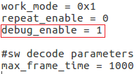

- push remote.cfg back
 # adb root
 # adb remount
 # adb push remote.cfg /vendor/etc/
 # adb shell
 m5_mbox:/ # chmod 644 /vendor/etc/remote.cfg
 m5_mbox:/ # remotecfg -c /vendor/etc/remote.cfg -d
 cfgdir = /vendor/etc/remote.cfg
 work_mode = 1
 repeat_enable = 0
 debug_enable = 1
 max_frame_time = 1000
- 3. Get the remote keycode
- Press your remote key one by one and then print the dmesg to get the remote custom_code and each remote key code.
# adb shell dmesg | grep framecode=

- custom_code = 0xfe01
- keycode = 0x00, 0x01, 0x09, 0x02, 0x0a, 0x05, 0x04 0x06, 0x03, 0x0b, 0x40, 0x48, 0x44
- 4. Modify remote.tab to map the scancode to android keycode
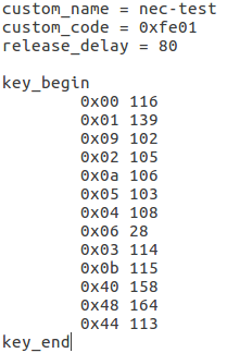

- push remote.tab and test each key whether works
 # adb root
 # adb remount
 # adb push remote.tab1 /vendor/etc/
 # adb shell
 m5_mbox:/ # chmod 644 /vendor/etc/remote.tab
 m5_mbox:/ # remotecfg -c /vendor/etc/remote.cfg -t /vendor/etc/remote.tab -d
 cfgdir = /vendor/etc/remote.cfg
 work_mode = 1
 repeat_enable = 0
 debug_enable = 1
 max_frame_time = 1000
 tabdir = /vendor/etc/remote.tab
 custom_name = nec-test
 fn_key_scancode = 0xffff
 cursor_left_scancode = 0xffff
 cursor_right_scancode = 0xffff
 cursor_up_scancode = 0xffff
 cursor_down_scancode = 0xffff
 cursor_ok_scancode = 0xffff
 custom_code = 0xfe01
 release_delay = 80
 map_size = 13
 key[0] = 0x74
 key[1] = 0x1008b
 key[2] = 0x90066
 key[3] = 0x20069
 key[4] = 0xa006a
 key[5] = 0x50067
 key[6] = 0x4006c
 key[7] = 0x6001c
 key[8] = 0x30072
 key[9] = 0xb0073
 key[10] = 0x40009e
 key[11] = 0x4800a4
 key[12] = 0x440071
- 5. Reboot the board
Linux
Prepare
- 1. Linux image support SDcard or EMMC bootup, but you should read the boot sequence at first.
- 2. Make sure bootable EMMC is formatted if you want bootup from SDcard, more info refer to Erase EMMC for SDcard Bootup
- 3. Make sure SDcard is formatted without Linux image flashed if you want bootup from EMMC and use Sdcard as storage.
- 4. Install bpi-tools on your Linux PC. If you can't access this URL or any other install problem, please go to bpi-tools source repo, download and install this tools manually.
 $ apt-get install pv
 $ curl -sL https://github.com/BPI-SINOVOIP/bpi-tools/raw/master/bpi-tools | sudo -E bash
- 5. Download Linux latest Linux Image, and confirm that the md5 checksum is correct.
- 6. Default login: pi/bananapi or root/bananapi
Install Image to SDcard
- 1. Install image with bpi-tools on Linux, plug SDcard to Linux PC and run
$ sudo bpi-copy xxx-bpi-m5-xxx.img.zip /dev/sdX
- 2. Install Image with dd command on Linux, umount SDcard device /dev/sdX partition if mounted automatically. Actually bpi-copy is the same as this dd command.
 $ sudo apt-get install pv
 $ sudo unzip -p xxx-bpi-m5-xxx.img.zip | pv | dd of=/dev/sdX bs=10M status=noxfer
- 3. Install Image with Etcher on Windows, Linux and MacOS.
- Balena Etcher is an opensource project by Balena, Flash OS images to SDcard and USB drive
Install Image to EMMC
- 1. Prepare a SDcard with Linux image flashed and bootup board with this SDcard.
- 2. Copy Linux image to udisk, plug the udisk to board and mount it.
- 3. Install with bpi-tools command
$ sudo bpi-copy xxx-bpi-m5-xxx.img.zip /dev/mmcblk0
- 4. Install with dd command, umount mmcblk0p1 and mmcblk0p2 partition if mounted automatically. Actually bpi-copy is the same as this dd command.
 $ sudo apt-get install pv
 $ sudo unzip -p xxx-bpi-m5-xxx.img.zip | pv | dd of=/dev/mmcblk0 bs=10M status=noxfer
- 5. After download complete, power off safely and eject the SDcard.
Build Linux Source Code
- 1. Get the Linux bsp source code
$ git clone https://github.com/BPI-SINOVOIP/BPI-M5-bsp
- 2. Build the bsp source code
- Please read the source code README.md
- 3. If you want build uboot and kernel separately, please download the u-boot the kernel only, get the toolchains, boot script and other configuration files from BPI-M5-bsp
DTB overlay
- 1. DTB overlay is used for 40pin gpios multi-function configuration and install in vfat boot partition, you can check the mount point with mount command.
 root@bananapi:~# ls /boot/firmware/overlays/
 custom_ir.dtbo      pwm_b-backlight.dtbo  spi0.dtbo
 ds3231.dtbo         pwm_c-beeper.dtbo     uart1_cts_rts.dtbo
 hifi_pcm5102a.dtbo  pwm_cd-c.dtbo         uart1.dtbo
 hifi_pcm5122.dtbo   pwm_cd.dtbo           uart2.dtbo
 i2c0.dtbo           pwm_ef.dtbo           waveshare_tft24_lcd.dtbo
 i2c1.dtbo           pwm_ef-f.dtbo         waveshare_tft35c_lcd.dtbo
 pwm_ab.dtbo         sdio.dtbo             waveshare_tft35c_rtp.dtbo
- 2. Update the overlays env in vfat BPI-BOOT/boot.ini to enable what you want. Default i2c0, spi0 and uart1 enabled.
 # Overlays to load
 # Example combinations:
 #   spi0 i2c0 i2c1 uart0
 #   hktft32
 #   hktft35
 setenv overlays "i2c0 spi0 uart1"
- 3. Must be restart the board for overlay dtb loaded.
WiringPi
- Note: This WiringPi only support set 40pin gpio to output, input or software pwm, for io functions as i2c, spi, pwm..., you must enable dtb overlay in boot.ini
- 1. Build and install wiringPi
 $ git clone https://github.com/BPI-SINOVOIP/amlogic-wiringPi
 $ cd amlogic-wiringPi
 $ chmod a+x build
 $ sudo ./build
- 2. Run gpio readall to show all 40pins status.

- 3. BPI GPIO Extend board and examples in amlogic-wiringPi/examples
- blinkall, blink all pin header gpios, no extend board.
- lcd-bpi, BPI LCD 1602 display module example.
- 52pi-bpi, BPI OLED Display Module example.
- matrixled-bpi, BPI RGB LED Matrix Expansion Module example.
- berryclip-bpi, BPI BerryClip Module
Other Development
Custom Linux Boot Logo
- Linux uboot limit boot logo fb size to 1080p60hz/1920x1080 default, so oversize resolution will not be supported by default image, but you can modify uboot source code to support it.
- 1. Prepare a 24bit bmp file and named boot-logo.bmp
- 2. Compress the bmp file to boot-logo.bmp.gz
$ gzip boot-logo.bmp
- 3. copy the target file to BPI-BOOT partition of linux image
$ cp boot-logo.bmp.gz /media/xxx/BPI-BOOT/
Custom Android Boot Logo
- Android bootloader limit boot logo fb display size is 1080p60hz/1920x1080 default, and android kernel dtb partition table limit boot logo partition size to 16MB default .
- 1. Prepare a 24bit bmp file and named boot-logo.bmp
- 2. Compress the bmp file to boot-logo.bmp.gz
$ gzip boot-logo.bmp
- 3. Download m5_android_bootlogo_tool.zip
- 4. Extract this tool
 $ unzip m5_android_bootlogo_tool.zip
 $ cd m5_android_bootlogo_tool/
 $ cp -a logo_img_files logo               //logo_img_files is the origin bootlogo resource in android source and copy from <android-source-dir>/devices/amlogic/bananapi_m5/log_img_files
 $ ls -l logo/
 -rwxr--r-- 1 dangku dangku 525054 Sep 25 16:54 bootup.bmp
 -rwxr--r-- 1 dangku dangku 525054 Sep 25 16:54 bootup_X3.bmp
 -rwxr--r-- 1 dangku dangku    184 May 19  2020 upgrade_bar.bmp
 -rwxr--r-- 1 dangku dangku 180072 May 19  2020 upgrade_error.bmp
 -rwxr--r-- 1 dangku dangku 180072 May 19  2020 upgrade_fail.bmp
 -rwxr--r-- 1 dangku dangku 180072 May 19  2020 upgrade_logo.bmp
 -rwxr--r-- 1 dangku dangku 180072 May 19  2020 upgrade_success.bmp
 -rwxr--r-- 1 dangku dangku    184 May 19  2020 upgrade_unfocus.bmp
 -rwxr--r-- 1 dangku dangku 180072 May 19  2020 upgrade_upgrading.bmp
- 5. Copy the boot-logo.bmp.gz
 $ cp boot-logo.bmp.gz logo/bootup.bmp
 $ cp boot-logo.bmp.gz logo/bootup_X3.bmp
- 6. Create target logo.img with img pack tool, the binary and related libs of m5_android_bootlogo_tool are copy from <android-source-dir>/out/host/linux-x86
$ ./logo_img_packer -r logo logo.img
- 7. Flash boot logo with fastboot
 $ adb root
 $ adb remount
 $ adb reboot fastboot
- Wait few seconds and check whether fastboot connected
 $ fastboot device
 1234567890      fastboot
 $ fastboot flashing unlock_critical
 $ fastboot flashing unlock
 $ fastboot flash logo logo.img
 $ fastboot reboot
Boot Sequence

- Check bootloader loaded from SDcard or EMMC at the beginning of the console debug messages
- 1. Rom load bootloader from SDcard (Linux log example)
 ...

 BL2 Built : 15:21:42, Mar 26 2020. g12a g486bc38 - gongwei.chen@droid11-sz

 Board ID = 1
 Set cpu clk to 24M
 Set clk81 to 24M
 Use GP1_pll as DSU clk.
 DSU clk: 1200 Mhz
 CPU clk: 1200 MHz
 Set clk81 to 166.6M
 board id: 1
 Load FIP HDR DDR from SD, src: 0x00010200, des: 0xfffd0000, size: 0x00004000, part: 0
 fw parse done
 PIEI prepare done
 fastboot data verify
 result: 255
 Cfg max: 12, cur: 1. Board id: 255. Force loop cfg
 DDR4 probe

 ...
- 2. Rom load bootloader from EMMC(Android Log example)
 ...

 Board ID = 1
 Set cpu clk to 24M
 Set clk81 to 24M
 Use GP1_pll as DSU clk.
 DSU clk: 1200 Mhz
 CPU clk: 1200 MHz
 Set clk81 to 166.6M
 eMMC boot @ 0
 sw8 s
 board id: 1
 Load FIP HDR DDR from eMMC, src: 0x00010200, des: 0xfffd0000, size: 0x00004000, part: 0
 fw parse done
 PIEI prepare done
 00000000
 emmc switch 1 ok
 ddr saved addr:00016000
 Load ddr parameter from eMMC, src: 0x02c00000, des: 0xfffd0000, size: 0x00001000, part: 0
 00000000

 ...
Erase EMMC for SDcard Bootup
- There are four possible scenarios should be pay attention to, EMMC already flashed Android image, EMMC already flashed Linux image, boot process hangup in BL2 and EMMC empty.
- 1. Bootable EMMC with Android image flashed
- a). Using usb burning tool, unplug the type-c usb cable while the download process at 7% formatting

- b). Using Android Fastboot tool, make sure the adb/fastboot tools is work on your PC before doing this.
   root@dangku-desktop:/tmp# adb root
   adbd is already running as root
   root@dangku-desktop:/tmp# adb remount
   remount succeeded
   root@dangku-desktop:/tmp# adb shell
   bananapi_m5:/ # reboot fastboot
- Wait a few seconds for board reboot to fastboot mode
   root@dangku-desktop:/tmp# fastboot devices
   1234567890	fastboot
   root@dangku-desktop:/tmp# fastboot flashing unlock_critical
   ...
   OKAY [  0.044s]
   finished. total time: 0.044s
   root@dangku-desktop:/tmp# fastboot flashing unlock
   ...
   OKAY [  0.047s]
   finished. total time: 0.047s
   root@dangku-desktop:/tmp# fastboot erase bootloader
   erasing 'bootloader'...
   OKAY [  0.059s]
   finished. total time: 0.059s
   root@dangku-desktop:/tmp# fastboot erase bootloader-boot0
   erasing 'bootloader-boot0'...
   OKAY [  0.036s]
   finished. total time: 0.036s
   root@dangku-desktop:/tmp# fastboot erase bootloader-boot1
   erasing 'bootloader-boot1'...
   OKAY [  0.035s]
   finished. total time: 0.035s
- c). Using uboot command, connect a debug console cable and press ESC while power on to enter uboot command line
   bananapi_m5_v1#amlmmc erase 1
   emmckey_is_protected(): protect
   start = 0,end = 57343
   start = 221184,end = 30535679
   Erasing blocks 0 to 8192 @ boot0
   start = 0,end = 8191
   Erasing blocks 0 to 8192 @ boot1
   start = 0,end = 8191
   bananapi_m5_v1#reset
   resetting ...
   SM1:BL:511f6b:81ca2f;FEAT:A0F83180:20282000;POC:F;RCY:0;EMMC:0;READ:0;CHK:1F;READ:0;CHK:1F;READ:0;CHK;
- These two ways actually erase the bootloader part of EMMC android, After bootup from SDcard Linux, You'd better format the whole EMMC by dd command.
- d). Using uboot reboot command to restart from SDcard once time, but Android in EMMC still exist completely. Connect a debug console cable and press ESC while power on to enter uboot command line, type "reboot sdboot" command, After reboot from SDcard Linux, you can format the whole EMMC by dd command and then flash the Linux image to EMMC.
bananapi_m5_v1#
- Insert the SDcard with Linux image flashed now.
   bananapi_m5_v1#reboot sdboot
   reboot mode: sdboot
   reboot dev: sd
   BPI: set rom boot from sdcard after reset
   before value = 0!
   after value = 4f5244c0!
   resetting ...
   SM1:BL:511f6b:81ca2f;FEAT:A0F83180:20282000;POC:F;RCY:0;OVD:2;SD?:0;SD:0;READ:0;0.0;CHK:0;
   bl2_stage_init 0x01
   ...
   board id: 1
   Load FIP HDR DDR from SD, src: 0x00010200, des: 0xfffd0000, size: 0x00004000, part: 0
   ...
- e). The simplest way is insert the SDcard with Linux image flashed before power on, the Android bootloader will check boot.ini file whether exist in SDcard vfat partition, so that the SDcard Linux will bootup. After bootup, you can format the whole EMMC by dd command and then flash the Linux image to EMMC.
   ...
   BPI: try boot from sdcard
   reading boot.ini
   5699 bytes read in 3 ms (1.8 MiB/s)
   ## Executing script at 01b00000
   ...
   reading Image.gz
   9143358 bytes read in 510 ms (17.1 MiB/s)
   reading meson64_bananapi_m5.dtb
   70850 bytes read in 8 ms (8.4 MiB/s)
   reading uInitrd
   11704481 bytes read in 655 ms (17 MiB/s)
   reading overlays/i2c0.dtbo
   223 bytes read in 6 ms (36.1 KiB/s)
   reading overlays/spi0.dtbo
   516 bytes read in 6 ms (84 KiB/s)
   reading overlays/uart1.dtbo
   225 bytes read in 5 ms (43.9 KiB/s)
- 2. Bootable EMMC with Linux image flashed
- a). Using uboot command, connect a debug console cable and press ESC while power on to enter uboot command line
bananapi_m5# mmc erase 0 1000
- b). Linux u-boot also check boot.ini file whether exist in SDcard vfat partition so that the SDcard Linux will bootup. After bootup, you can format the whole EMMC by dd command or flash the Linux image directly to EMMC.
- 3. A extreme situation is bootloader or uboot corrupted, Rom load it from EMMC but hangup in u-boot or BL2, for example the boot process will hangup in BL2 of EMMC if dram init failed, The only way is format the EMMC with usb burning tool, or download the Android image completely and then try other ways to erase EMMC or flash Linux image to EMMC.
- 4. Rom will try to load bootloader from SDcard directly if EMMC is empty.
Erase Emmc Android by dd command
- If the board is flashed android before, the whole emmc must be erased by these commands if you want bootup it with SDcard Linux image.
 $ sudo dd if=/dev/zero of=/dev/mmcblk0boot0 bs=1M status=noxfer
 $ sudo dd if=/dev/zero of=/dev/mmcblk0boot1 bs=1M status=noxfer
 $ sudo dd if=/dev/zero of=/dev/mmcblk0 bs=1M status=noxfer
 $ sync
Wifi/BT support
- 1. Android test and support.
 rtl8723bu wifi/bt(usb)
 rtl8188eu wifi(usb)
 rtl8821cu wifi/bt(usb)
 rtl8822cs wifi/bt(sdio/uart)
 rtl8814au wifi(usb), please get the aircrack-ng driver and install.
- How to enable Android Wifi/BT
- USB type: Plug-in the usb dongle to usb host port and reboot the system, After bootup, you can enable or disable wifi and bluetooth in Settings app.
- SDIO/UART type: Connect the hardware module to 40pin header correctly and configure the Android DTB overlay to enable it.
- Note: Android is not support that ethernet and wifi are both connected at the same time, Ethernet have a higher prioprity than wifi, it means wifi can't connect network if ethernet already connected, and wifi will drop connection if ethernet cable plugin.
- 2. Linux test and support.
 rtl8188eu wifi(usb)
 rtl8192eu wifi(usb)
 rtl8723bu wifi/bt(usb)
 rtl8811au wifi(usb)
 rtl8812au wifi(usb)
 rtl8812bu wifi(usb)
 rtl8821cu wifi/bt(usb)
 rtl8822cs wifi/bt(sdio/uart)
- How to enable Linux Wifi
- Wifi module drivers are already prebuild in the release images.
- USB type: Plug-in the usb dongle to usb host port and driver will be loaded automatically.
- SDIO/UART type:
- 1). Connect the hardware module to 40pin header correctly.
- 2). Configure the dtb overlay
  # Overlays to load
  # Example combinations:
  #   spi0 i2c0 i2c1 uart0
  #   hktft32
  #   hktft35
  setenv overlays "wifi_bt_rtl8822cs"
- 3). Add the wifi module name to /etc/modules for loaded automatically next boot.
- How to enable Linux Bluetooth
- 1). Please download rtk-linux-bt-driver source code, build and install usb or uart rtk linux bluetooth drivers/firmwares to your image.
- 2). For USB type, plug-in the usb dongle to usb host port and driver will be loaded automatically.
- 3). For UART type, Configure the dtb overlay as the same as wifi before install the bluetooth drivers/firmwares. hci_uart driver will be loaded when rtk-hciuart.service start.
Linux Server Image Network Configuration
- Linux Wifi STA mode
- A sample wifi sta mode netplan configuration file, 01-wlan0-sta.yaml
network:
  version: 2
  renderer: networkd
  wifis:
    wlan0:
      dhcp4: true
      access-points:
        "bananapi":
           password: "123456789"
- Linux Wifi AP mode
- 1. Prepare the setup the wifi adater correctly.
- 2. Get the wifi adapter Band, Frequencies, Channel, HT Capability, VHT Capability or other properties
$ iw list
- 3. Manage wifi access point mode with Netplan and Network-Manager.
- Install NetworkManager because ap is only supported with NetworkManager renderer
$ sudo apt install network-manager
- A sample 2.4G wifi ap mode netplan configuration file, 01-wlan0-ap-2.4g.yaml
network:
version: 2
renderer: NetworkManager
wifis:
  wlan0:
    dhcp4: no
    access-points:
      "bananapi":
         mode: ap
         band: 2.4GHz
         channel: 6
         auth:
           key-management: psk
           password: "123456789"
- A sample 5G wifi ap mode netplan configuration file, 01-wlan0-ap-5g.yaml
network:
version: 2
renderer: NetworkManager
wifis:
  wlan0:
    dhcp4: no
    access-points:
      "bananapi":
         mode: ap
         band: 5GHz
         channel: 36
         auth:
           key-management: psk
           password: "123456789"
- 4. Manage wifi access point mode with Netplan and Hostapd.
- 1). Create a netplan configuration file, 01-wlan0-ap-hostapd.yaml
network:
version: 2
renderer: networkd
ethernets:
  wlan0:
    dhcp4: no
    addresses:
      - 192.168.11.1/24
- 2). Install hostapd
$ sudo apt install hostapd
- Create hostapd configuration file /etc/hostapd/hostapd.conf, for example
interface=wlan0
ssid=bananapi

driver=nl80211

auth_algs=1
wpa=2
wpa_passphrase=123456789
wpa_key_mgmt=WPA-PSK
rsn_pairwise=CCMP

#bridge=br0
beacon_int=500
#SSID not hidden
ignore_broadcast_ssid=0

hw_mode=a
channel=36
max_num_sta=8

### IEEE 802.11n
ieee80211n=1
#require_vht=0
ht_capab=[HT20][HT40+][SHORT-GI-20][SHORT-GI-40][SHORT-GI-80][DSSS_CCK-40]

### IEEE 802.11ac
ieee80211ac=1
#require_vht=0
#vht_capab=[MAX-MPDU-3895][SHORT-GI-80][SU-BEAMFORMEE]
#vht_oper_chwidth=1
#vht_oper_centr_freq_seg0_idx=42

### WMM
wmm_enabled=1
- 3). To support 80MHz channel width you need load driver with rtw_vht_enable=2 option, Or you can create /etc/modprobe.d/8822cs.conf with content
options 88x2cs rtw_vht_enable=2
- 4). Install and configure dhcp server service, use isc-dhcp-server for example
$ sudo apt install isc-dhcp-server
- Configure dhcp server interface in /etc/default/isc-dhcp-server
# On what interfaces should the DHCP server (dhcpd) serve DHCP requests?
#       Separate multiple interfaces with spaces, e.g. "eth0 eth1".
INTERFACESv4="wlan0"
- Configure dhcp subnet and dns in /etc/dhcp/dhcpd.conf
...
option domain-name "example.org";
option domain-name-servers 8.8.8.8, 114.114.114.114;
...
# No service will be given on this subnet, but declaring it helps the
# DHCP server to understand the network topology.
subnet 192.168.11.0 netmask 255.255.255.0 {
  range dynamic-bootp 192.168.11.1 192.168.11.100;
  option broadcast-address 192.168.11.255;
  option routers 192.168.11.1;
}
- 5). Start Service
$ sudo hostapd /etc/hostapd/hostapd.conf -B
$ sudo systemctl restart isc-dhcp-server
- 6). Routing configuration.
sysctl net.ipv4.ip_forward=1
iptables -t nat -A POSTROUTING -s 192.168.11.0/24 -o eth0 -j MASQUERADE
Cloud-init&Snap
- Cloud-init and Snap service are enabled default, you can disable or remove them.
- 1. disable or remove cloud-init
$ sudo touch /etc/cloud/cloud-init.disabled
- or
$ sudo apt purge cloud-init
- 2. disable or remove snap
$ sudo apt purge snapd
Install Docker Engine
- Install Docker Engine on Ubuntu 20.04 Server
- 1. Set up the repository
- Update the apt package index and install packages to allow apt to use a repository over HTTPS:
 $ sudo apt-get update
 $ sudo apt-get install apt-transport-https ca-certificates curl gnupg lsb-release
- Add Docker’s official GPG key:
$ curl -fsSL https://download.docker.com/linux/ubuntu/gpg | sudo gpg --dearmor -o /usr/share/keyrings/docker-archive-keyring.gpg
- Set up the stable repository
 $  echo \
    "deb [arch=arm64 signed-by=/usr/share/keyrings/docker-archive-keyring.gpg]https://download.docker.com/linux/ubuntu \
    $(lsb_release -cs) stable" | sudo tee /etc/apt/sources.list.d/docker.list > /dev/null
- 2. Install Docker Engine
 $ sudo apt-get update
 $ sudo apt-get install docker-ce docker-ce-cli containerd.io
- 3. Verify the Docker Engine is installed correctly by running the hello-world image.
$ sudo docker run hello-world

Install docker with a simple command
$ curl -sSL get.docker.com | sudo sh
Install Docker Engine on other Linux distributions