Difference between revisions of "Getting Started with BPI-M4 Berry"
(→Build Android Source Code) |
(→Custom IR) |
||
| Line 35: | Line 35: | ||
:[[File:m4-berry_android_5.jpg]] | :[[File:m4-berry_android_5.jpg]] | ||
| + | |||
| + | ===Build Android Source Code=== | ||
| + | |||
| + | :Please read the source code [https://github.com/BPI-SINOVOIP/BPI-H618-Android12/blob/master/README.md README.md] | ||
===Custom IR=== | ===Custom IR=== | ||
Revision as of 20:03, 21 January 2024


Contents
- 1 Development
- 1.1 Android
- 1.2 Linux
- 1.2.1 Prepare
- 1.2.2 Install Image to SDcard
- 1.2.3 Install Image to eMMC
- 1.2.4 Erase eMMC
- 1.2.5 Ubuntu Desktop
- 1.2.6 Debug UART
- 1.2.7 SSH
- 1.2.8 NoMachine Remote Desktop
- 1.2.9 WiFi
- 1.2.10 Set static IP, DNS
- 1.2.11 Network time synchronization
- 1.2.12 View hardware temperature
- 1.2.13 Modify HDMI output resolution
- 1.2.14 Use USB disk
- 1.2.15 Use Audio Devices
- 1.2.16 Use Bluetooth
- 1.2.17 Use IR Receiver
- 1.2.18 Transfer files
- 1.2.19 40 pin interface GPIO, I2C, UART, SPI, and PWM testing
Development
Android
Prepare
- 1. Download latest Android image.
- 2. Download and Install Allwinner Image Download Tools, PhoenixSuit is for window.
- 3. Type-C cable, 5V power supply.
Install Image with USB tool
- 1. Open PhoenixSuit, click the Firmware icon to switching to firmware download panel, then click Image button and choose the Android Image file.


- 2. Press and hold the SW2 button on M4 Berry while connecting to the computer using type-c, popup a warning dialog.Press Yes.

- 3. Download

- 4. Download finish

Build Android Source Code
- Please read the source code README.md
Custom IR
- Wiki images support NEC protocol default.
- 1. Execute getevent -l | grep MSC_SCAN in the serial port or adb shell, then press the corresponding button on the remote control to obtain the device ID and scancode.

- The MSC_SCAN data is 32 bits.
- Bits [31:24] represent the key press status, where 0 indicates release, and 1 indicates press.
- Bits [23:8] represent the device ID. Use this ID to generate a keylayout file named customer_ir_xxxx.kl. For example, in this case, it would be customer_ir_fe01.kl.
- Bits [7:0] represent the scancode.
- 2. Based on the results of step one, create a new file named customer_ir_xxxx.kl with the following content:

- Map the scancodes in the second column to Android keycodes.
- 3. Use the adb command to push customer_ir_xxxx.kl to the system.
 $ adb root
 $ adb remount
 $ adb push customer_ir_xxxx.kl  /system/usr/keylayout/
 $ adb reboot
- For source code porting, put the customer_ir_xxxx.kl to vendor/w/common/hardware/input/multi_ir/keylayout/ directory and build the source code.
Custom Logo
- 1. Boot logo
- Rename the logo file to bootlogo.bmp and put it in longan/device/config/chips/h618/boot-resource/boot-resource/ directory.
- 2. Bootanimation logo
- Put bootanimation.zip to device/softwinner/apollo/common/media/bootanimation/ directory.
- 3. Launcher logo for Box variant image
- Create a 270x110, 32 bit depth, png image and rename it to aw_logo.png, put it in vendor/aw/common/package/TVLauncher/res/drawable-xhdpi/ directory.
- Then build the source code and flash the image to your board.
Linux
Prepare
- 1. Linux image support SDcard or EMMC bootup, and will boot from the SD card first.
- 2. It’s recommended to use A1 rated cards, 8GB at least.
- 3. Make sure bootable EMMC is formatted if you want bootup from SDcard.
- 4. Make sure SDcard is formatted without Linux image flashed if you want bootup from EMMC and use Sdcard as storage.
- 5. Download latest bananapi ubuntu/debian images, and confirm that the md5 checksum is correct.
- 6. Default login: pi/bananapi or root/bananapi
- 7. The wiki guide is only for bananapi ubuntu/debian images.
- 8. USB-Serial (3.3V). Baud: 115200.
Install Image to SDcard
- 1. Install Image with Balena Etcher on Windows, Linux and MacOS.
- Balena Etcher is an opensource GUI flash tool by Balena, Flash OS images to SDcard or USB drive.

Install Image to eMMC
1. Make sure that the Linux image has been burned into an SD card and started normally.
2. Enter the following command in the terminal:
sudo bananapi-config
3. By default, select the first item continuously and press the Enter key to install the Linux system image on the eMMC.


4. The last step is to shut down the computer. At this time, disconnect the power supply, remove the SD card, and power on again to boot from eMMC.
Erase eMMC
1. Make sure the Linux image has been burned into an SD card and insert the SD card. By default it will boot from the SD card.
2. Enter the command lsblk in the terminal to list the block device information in the system, such as hard disks, partitions, disks, etc.
pi@bpi-m4berry:~$ lsblk
NAME MAJ:MIN RM SIZE RO TYPE MOUNTPOINTS
mmcblk0 179:0 0 7.4G 0 disk
└─mmcblk0p1 179:1 0 7.2G 0 part /var/log.hdd
                                        /
mmcblk1 179:32 0 7.3G 0 disk
└─mmcblk1p1 179:33 0 7.3G 0 part
mmcblk1boot0 179:64 0 4M 1 disk
mmcblk1boot1 179:96 0 4M 1 disk
zram0 252:0 0 993.2M 0 disk [SWAP]
zram1 252:1 0 50M 0 disk /var/log
zram2 252:2 0 0B 0 disk
3. mmcblk0 is the SD card and mmcblk1 is the eMMC. Enter the following command in the terminal to erase the eMMC. This process takes several minutes and is irreversible. Be careful to back up important data.
sudo dd if=/dev/zero of=/dev/mmcblk1
Ubuntu Desktop
- 1. Using the Ubuntu desktop version system image, you can get a graphical operation interface.
- 2. You need to prepare a monitor with an HDMI interface and an HDMI cable.
- 3. Use an HDMI cable to connect the monitor and BPI-M4 Berry, switch the monitor input interface to the corresponding HDMI interface, power on, and wait a moment to see the desktop.

Debug UART
- 1. Prepare a 3.3v USB to TTL module.
- 2. Use the USB to TTL module to connect the PC USB port and the Debug UART port on the board.
- 3. Open a serial terminal software on the PC, such as mobaxterm or putty.
- 4. Taking mobaxterm as an example, after setting the serial port number and 115200 baud rate, you can open the BPI-M4 Berry UART terminal.


SSH
- 1. Prepare a network cable and a router.
- 2. Use a network cable to connect the LAN port of the router to the BPI-M4 Berry, and also connect the PC to another LAN port.
- 3. Check the IP address of BPI-M4 Berry on the router management interface, or use the following command on the BPI-M4 Berry UART terminal to check the IP address.
ifconfig
  eth0: flags=4163<UP,BROADCAST,RUNNING,MULTICAST> mtu 1500
        inet 192.168.3.10 netmask 255.255.255.0 broadcast 192.168.3.255
        inet6 fe80::3e1f:688f:81ab:d8b7 prefixlen 64 scopeid 0x20<link>
        ether 02:00:54:a0:d6:a6 txqueuelen 1000 (Ethernet)
        RX packets 553 bytes 92549 (92.5 KB)
        RX errors 0 dropped 0 overruns 0 frame 0
        TX packets 329 bytes 26023 (26.0 KB)
        TX errors 0 dropped 0 overruns 0 carrier 0 collisions 0
        device interrupt 42
- 4. Open an SSH terminal software on the PC, such as mobaxterm or putty.
- 5. Taking mobaxterm as an example, fill in the obtained IP address, such as 192.168.3.10 above, in the IP address column and 22 in the Port port.

- 6. Open the SSH terminal and enter the login username/password: pi/bananapi or root/bananapi. There will be no prompt when entering the password. Please enter it normally and press Enter when finished.

NoMachine Remote Desktop
- 1. Make sure BPI-M4 Berry is connected to the Internet and use the following command to download the nomachine DEB installation package in the system.
wget https://download.nomachine.com/download/8.9/Arm/nomachine_8.9.1_1_arm64.deb
- 2. Or open NoMachine for ARM - arm64 download page in a PC browser, download the DEB installation package, and then copy it to BPI-M4 Berry user directory through SSH or USB disk.
- 3. After the download is completed, install it through the following command. Note that the file name is based on the actual downloaded file name.
sudo dpkg -i nomachine_8.9.1_1_arm64.deb
- 4. PC side also needs to download and install NoMachine. NoMachine download page Select the installation package suitable for the PC operating system, download it locally and complete the installation.
- 5. Pay attention to keeping the PC and BPI-M4 Berry in the same LAN. You can try SSH connection first to ensure normal communication within the LAN.
- 6. Open NoMachine on the PC, click the Add button, enter the IP address of BPI-M4 Berry in the Host bar in the window after the jump, and then click the Add button.

- 7. Click the recognized port icon, enter the username/password in the new window that pops up, and then click the OK button.


- 8. After completing the subsequent settings, you can see the desktop.

- 9. If no device is connected to the HDMI interface, the NoMachine remote desktop will display a black screen. It is recommended to keep the HDMI connection or connect an HDMI decoy device.
WiFi
- Use the nmcli command to scan WiFi hotspots, connect to hotspots, and create AP hotspots.
  nmcli device #List devices
  nmcli device wifi list # List available wifi access points, list can be omitted
  nmcli device wifi connect [SSID] password [PASSWORD] # Connect to the hotspot mySSID. After the connection is successful, the configuration file will be automatically generated. If you want to connect again in the future, you can use the nmcli connection up [SSID] command.
  nmcli device disconnect [device name] # Disconnect wifi, use the wifi device name displayed in the nmcli device command
  nmcli device wifi hotspot con-name [NAME] ifname [device name] ssid [SSID] password [PASSWORD] # Create AP hotspot
  nmcli connection show #List network connection configuration
  nmcli connection down [NAME] # Deactivate a connection
  nmcli connection up [NAME] # Activate a connection
  nmcli connection delete [SSID] #Delete a configuration and no longer save information and automatically connect
  nmcli radio wifi off # Turn off wifi
  nmcli radio wifi on # Turn on wifi
Set static IP, DNS
- 1. To set a static IP, you need to maintain the connection first. If you want to set an Ethernet static IP, you must first maintain the Ethernet connection; if you want to set a wireless network static IP, you must first maintain a connection to a WIFI.
- 2. If the upper-level router has assigned the IP address you want to set to other devices, please change it to an idle IP, or ask other devices to give up the IP.
- 3. Use the nmcli connection show command to display all connections, for example:
  pi@bpi-m4berry:~$ nmcli connection show
  NAME UUID TYPE DEVICE
  TP-LINK_5G_7747 e4a49726-adf1-44d7-a621-0e3af96cc390 wifi wlx2cc3e6acd5d7
  Wired connection 1 612eda94-55dc-3c85-b05e-f16c41775b4e ethernet --
- 4. Use the nmcli connection show [NAME] command to display all the properties of a specific connection, such as:
nmcli connection show TP-LINK_5G_7747 #If you want to see Ethernet, change to Wired connection 1
  #Only list three common items
  ipv4.dns: 192.168.3.1 #The default is the gateway address
  ipv4.addresses: 192.168.3.10/24 #The default is the IP address assigned by the router DHCP
  ipv4.gateway: 192.168.3.1 #Gateway address, the default is the IP address of the router
- 5.Set static IP:
nmcli connection modify TP-LINK_5G_7747 ipv4.addresses 192.168.3.2
- 6.Set DNS:
nmcli connection modify TP-LINK_5G_7747 ipv4.dns 8.8.8.8 #Google DNS
- 7.Reset:
reboot
- 8. After restarting, check whether the modification is successful:
  ifconfig
  nmcli connection show TP-LINK_5G_7747
Network time synchronization
- Chrony is an open source free Network Time Protocol NTP client and server software. It allows the computer to keep the system clock synchronized with the clock server (NTP), thus allowing your computer to maintain accurate time. Chrony can also be used as a server software to provide time synchronization services for other computers.
timedatectl set-ntp false #Disable NTP-based network time synchronization
  sudo apt install chrony #Install chrony
  systemctl start chrony #Start chrony
  systemctl enable chrony
  systemctl status chrony
  systemctl restart chrony #Restart service
  timedatectl status #View time synchronization status
  timedatectl list-timezones #View time zone list
  timedatectl set-timezone Asia/Shanghai #Modify time zone
  timedatectl set-ntp true #Enable NTP network time synchronization
  date #View time
  sudo hwclock -r #View hardware clock
View hardware temperature
Enter the following command to view the temperature data returned by the sensor built into the chip on the BPI-M4 Berry board.
sensors
Modify HDMI output resolution
- When using the Ubuntu desktop operating system, you can find the Displays column in Settings and modify the resolution.

Use USB disk
- 1. Prepare a USB disk that has been partitioned normally and insert it into the USB interface of BPI-M4 Berry.
- 2. In the Ubuntu desktop version, you can see that the USB disk has been recognized and can be opened in the file manager, or partition management can be performed through the GParted tool.

- 3. In the terminal, mount the USB disk to the local directory:
  mkdir mnt #Create a separate directory in the ~/user directory for mounting for easy management
  cat /proc/partitions | grep "sd*" #List partitions starting with sd
  sudo mount /dev/sda1 ~/mnt/ #Mount /dev/sda1 to ~/mnt/
  ls ~/mnt/ #After mounting, you can list the files in the USB disk
  sudo umount -v /dev/sda1 #umount, then you can remove the USB disk
Use Audio Devices
- Prepare an audio file and copy it to the BPI-M4 Berry Ubuntu desktop system through a USB flash drive or SSH.
HDMI audio
- 1. Prepare a monitor with HDMI audio input function, turn on the relevant functions in the monitor settings, and use an HDMI cable to connect the monitor.
- 2. Set the output device to HDMI Audio in the Sound column of the settings.

- 3.Play audio.

3.5mm audio jack
- 1. Prepare a headset or other audio device that uses a 3.5mm plug, insert the plug into the 3.5mm jack of BPI-M4 Berry.
- 2. Set the output device to Audio Codec in the Sound column of the settings.

- 3. Play audio.
Terminal command to play audio files
aplay -l #List devices
aplay -D hw:0,0 [path] #Play the audio file of the specified path
Use Bluetooth
- 1. Open settings in the Ubuntu desktop and connect a Bluetooth device, such as a Bluetooth mouse or keyboard, in the Bluetooth bar.

- 2. The method to connect the Bluetooth device through the command line in the terminal is as follows:
pi@bpi-m4berry:~$ sudo bluetoothctl #Open the Bluetooth device management tool
[sudo] password for pi:
Agent registered
[CHG] Controller 2C:C3:E6:AC:D5:D8 Pairable: yes
[bluetooth]# power on #Start the Bluetooth function, power off to turn it off
Changing power on succeeded
[bluetooth]# discoverable on #Allow this device to be discovered
Changing discoverable on succeeded
[CHG] Controller 2C:C3:E6:AC:D5:D8 Discoverable: yes
[bluetooth]# pairable on #Allow device pairing
Changing pairable on succeeded
[bluetooth]# scan on #Start scanning
Discovery started
[CHG] Controller 2C:C3:E6:AC:D5:D8 Discovering: yes
[NEW] Device D4:C4:85:A5:C6:B1 Logitech Pebble #The MAC address and device name of a Bluetooth mouse
[CHG] Device D4:C4:85:A5:C6:B1 TxPower: 4
[bluetooth]# pair D4:C4:85:A5:C6:B1 #Pair the MAC address of the Bluetooth device you want to connect to
Attempting to pair with D4:C4:85:A5:C6:B1
[CHG] Device D4:C4:85:A5:C6:B1 Connected: yes
[DEL] Device A4:C1:38:9B:F6:FD SLPO20N20200059
[CHG] Device D4:C4:85:A5:C6:B1 UUIDs: 00001800-0000-1000-8000-00805f9b34fb
[CHG] Device D4:C4:85:A5:C6:B1 UUIDs: 00001801-0000-1000-8000-00805f9b34fb
[CHG] Device D4:C4:85:A5:C6:B1 UUIDs: 0000180a-0000-1000-8000-00805f9b34fb
[CHG] Device D4:C4:85:A5:C6:B1 UUIDs: 0000180f-0000-1000-8000-00805f9b34fb
[CHG] Device D4:C4:85:A5:C6:B1 UUIDs: 00001812-0000-1000-8000-00805f9b34fb
[CHG] Device D4:C4:85:A5:C6:B1 UUIDs: 00010000-0000-1000-8000-011f2000046d
[CHG] Device D4:C4:85:A5:C6:B1 ServicesResolved: yes
[CHG] Device D4:C4:85:A5:C6:B1 Paired: yes
Pairing successful #pairing successfully
[CHG] Device D4:C4:85:A5:C6:B1 Modalias: usb:v046DpB021d0007
[bluetooth]# exit #Exit the Bluetooth device management tool
pi@bpi-m4berry:~$
Use IR Receiver
- 1. You need to prepare an infrared remote control using NEC format.
- 2. Enter the following command in the terminal to start receiving infrared signals.
sudo ir-keytable -c -p NEC -t
  Old keytable cleared
  Protocols changed to nec
  Testing events. Please, press CTRL-C to abort.
  258.553895: lirc protocol(nec): scancode = 0x45
  258.553926: event type EV_MSC(0x04): scancode = 0x45
  258.553926: event type EV_SYN(0x00).
  260.667648: lirc protocol(nec): scancode = 0x46
  260.667671: event type EV_MSC(0x04): scancode = 0x46
  260.667671: event type EV_SYN(0x00).
  260.719552: lirc protocol(nec): scancode = 0x46 repeat
  260.719568: event type EV_MSC(0x04): scancode = 0x46
  260.719568: event type EV_SYN(0x00).
  273.263728: lirc protocol(nec): scancode = 0x47
  273.263753: event type EV_MSC(0x04): scancode = 0x47
  273.263753: event type EV_SYN(0x00).
  273.315591: lirc protocol(nec): scancode = 0x47 repeat
  273.315608: event type EV_MSC(0x04): scancode = 0x47
  273.315608: event type EV_SYN(0x00).
For other commands and specific application methods, please see ir-keytable reference document
Transfer files
scp
scp (secure copy) command in Linux system is used to copy file(s) between servers in a secure way.
The SCP command or secure copy allows the secure transferring of files between the local host and the remote host or between two remote hosts.
It uses the same authentication and security as it is used in the Secure Shell (SSH) protocol.
You can copy files from a Windows terminal to a Linux system on the same LAN. Just make sure the Open SSH client is turned on and can be viewed in Settings > Applications > Optional Features.
If you want to copy files from Windows systems to Linux systems, you also need to enable the Open SSH server.

The scp command format is:
scp [optionals] file_source file_target
- 1.[optionals] is an optional parameter, such as -r, which can be used to copy the entire directory recursively.
- 2.file_source The file or directory to be copied.
- 3.file_target will copy the past path and rename it if a specific file name is entered at the end.
Take copying local files from a Windows system to a Linux system as an example. In the Windows terminal, enter:
PS D:\temp\temp_4> scp ".\hello.txt" [email protected]:"/home/pi/Downloads/"
You can also copy files in the Linux system to the local computer in the Windows terminal:
PS D:\temp\temp_4> scp [email protected]:"/home/pi/Downloads/hello.txt" "D:\temp\temp_4"
- Where [email protected] is the user name in the Linux system and the IP address of the BPI-M4 Berry in the LAN.
- Where :"/home/pi/Downloads/hello.txt" is the file path in the Linux system.
- Where "D:\temp\temp_4" is the path in Windows system.
mobaxterm
Files can be managed through a graphical interface using mobaxterm or other similar software.
As shown in the figure below, after establishing an SSH connection in mobaxterm, a file management window will appear on the left side of the interface, which supports copying and pasting by dragging and dropping files.

40 pin interface GPIO, I2C, UART, SPI, and PWM testing
GPIO
Control the GPIO port to light up the LED light.
Set the high and low levels of GPIO

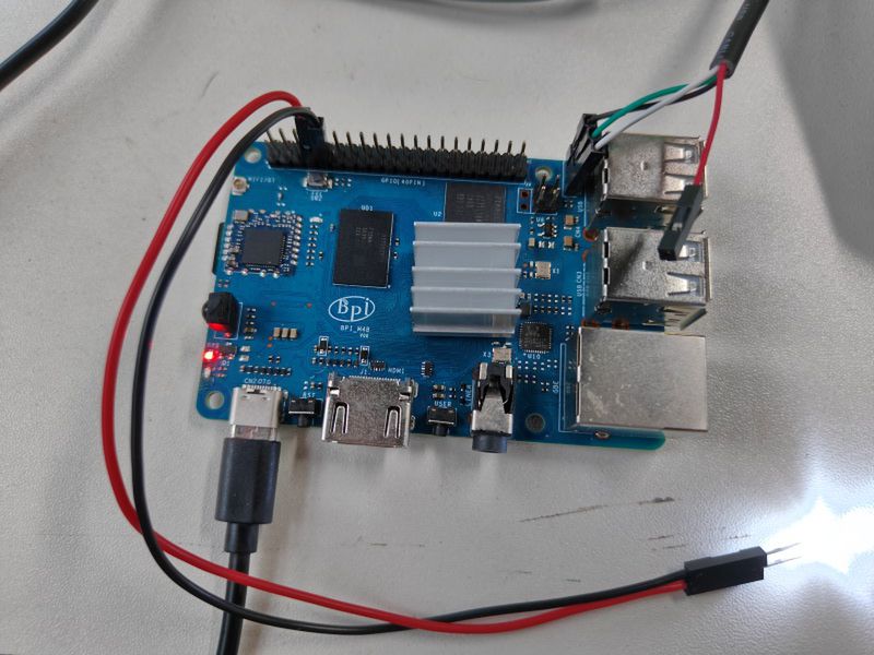
The following is a demonstration using 7 pin.
Insert the LED light and you can see that it is not lit up.

- 1.Execute
gpio mode 2 out
- to set it to output mode.
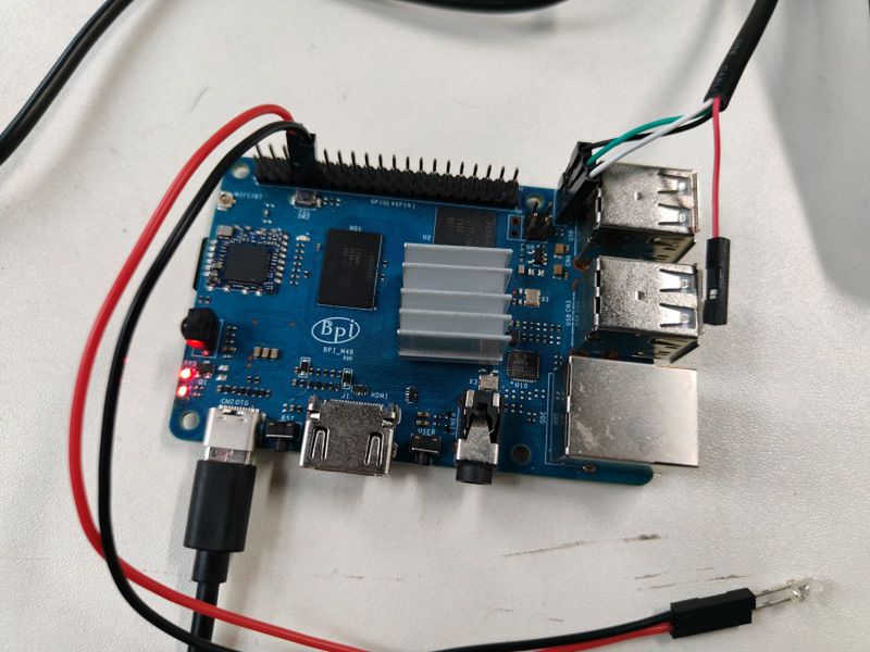
- 2.Execute
gpio write 2 1
- You can see that the LED light has been turned on.

- 3.Execute
gpio write 2 0
- You can see that the LED light has been turned off.
Set pull-up and pull-down resistors
- 1.Firstly, it is necessary to set the GPIO port to input mode
gpio mode 2 in
- 2.Then set the GPIO port as an pull-up resistor
gpio mode 2 up
- The LED light is lit up again
- 3.Finally, set the GPIO port to dropdown mode
gpio mode 2 down
- The LED light goes out again
I2C
According to the schematic diagram, the available i2cs are i2c3 and i2c4

- 1.Execute
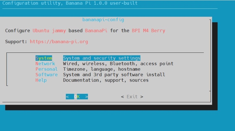
sudo bananapi-config
- 2.Select "System"

- 3.Select "Hardware"
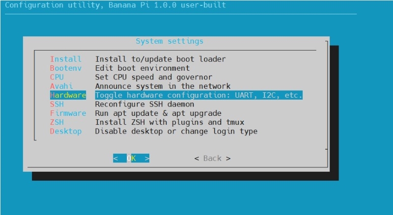

- 4.Use the keyboard directional keys to move, then use the spacebar to select.Select "pg-i2c3"and"pg-i2c4"
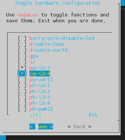

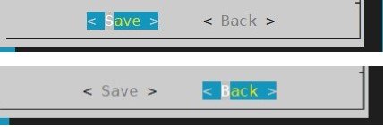
- 5.Select "Save", then select "Back"

- 6.Finally, choose Reboot.
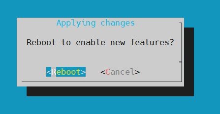

- 7.After restarting, check if there are i2c-3 and i2c-4 nodes.
pi@bpi-m4berry:~$ ls /dev/i2c-3
/dev/i2c-3
pi@bpi-m4berry:~$ ls /dev/i2c-4
/dev/i2c-4
- 8. Execute
cd /usr/src/wiringPi/examples/
gcc ./oled_demo.c -o oled -lwiringPi
- 9.Connect the i2c device to the pin of i2c3. Execute
sudo ./oled /dev/i2c-3

- 10.Connect the i2c device to the pin of i2c4. Execute
sudo ./oled /dev/i2c-4

UART
By reviewing the schematic, it can be found that the available uart are uart1 and uart5.

- 1.Uart1 and Uart5 is closed by default and needs to be opened. Execute
sudo bananapi-config
- 2.Select "System"
- 3.Select "Hardware"
- 4.Use the keyboard directional keys to move, then use the spacebar to select.If you want to use uart1,select"pg-uart1".If you want to use uart5,select"ph-uart5"
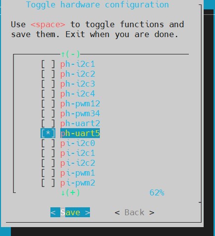

- 5.Select "Save", then select "Back"
- 6.Finally, choose Reboot.
- 7.After restarting, check if there are ttyS5 nodes.
pi@bpi-m4berry:~$ ls /dev/ttyS5
/dev/ttyS5
- 8:Short circuit uart1 pin or uart5 and execute
gpio serial /dev/ttyS1


SPI
By reviewing the schematic, it can be found that the available spi is spi1.

- 1.Execute
sudo bananapi-config
- 2.Select "System"
- 3.Select "Hardware"
- 4.Use the keyboard directional keys to move, then use the spacebar to select.Select "spi1-cs1-spidev"
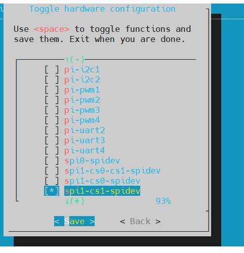

- 5.Select "Save", then select "Back"
- 6.Finally, choose Reboot.
- 7.After restarting, check if there are SPI nodes.
pi@bpi-m4berry:~$ ls /dev/spidev1.1
/dev/spidev1.1
- 8.Execute
sudo spidev_test -v -D /dev/spidev1.1

- It can be seen that TX and RX are different. So, we need to short-circuit MOSI and MISO and execute the command again.
