Getting Started with M5/M2Pro
Contents
Introduction
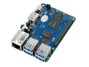
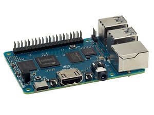
Banana Pi M5 is a new generation single board computer design , use Amlogic S905X3 Quad-Core Cortex-A55 (2.0xxGHz) Processor. Mali-G31 MP2 GPU with 4 x Execution Engines (650Mhz). support 4GB LPDDR4 and 16G eMMC flash. it have 4 USB 3.0 port,1GbE LAN port.
specifications
- SoC – Amlogic S905X3 quad-core Cortex-A55 processor @ up to 2.0 GHz with
- Mali-G31 MP2 GPU @ 650Mhz
- System Memory – 4GB LPDDR4
- Storage – 16GB eMMC flash (option up to 64GB), MicroSD slot up to 2TB
- Video Output – HDMI 2.1 up to 4Kp60 with HDR, CEC, EDID
- Audio – 3.5mm audio jack, digital HDMI audio
- Connectivity – Gigabit Ethernet
- USB – 4x USB 3.0 ports via VL817 hub controller, 1x USB-C port (for power only?)
- Expansion – 40-pin Raspberry Pi header with 28x GPIO, UART, I2C, SPI, PWM, and power signal (+5V, +3.3V, GND).
- Debugging – 3-pin debug header
- Misc – Reset, Power, and U-boot button; power and activity LED’s; IR receiver
- Power Supply – 5V @3A via USB Type-C port
- Dimensions – 92x60mm (Not the same as Raspberry Pi PCB size, but they probably included the connectors during measurement)
- Weight – 48grams
development
Prepare
- 1. Prepare a usb-serial cable, a 5V/2A adaptor with type-c power supply. The serial cable is used for console debug and type-c cable is used for android image download and ADB debug.
- 2. Prepare a SDcard at least 8GB for linux development, android only support emmc boot.
- 3. The SOC rom first boot sequence is emmc, so board can't bootup from SDcard if the emmc is bootable with any image flashed, more info about the image boot sequence please refer to board boot flow.
- 4.
Android
Prepare
- 1. Download and install the AML Usb Burning Tool for android image download via type-c, only support windows.
- 2. Download the AML Burn Card Maker tool for create a bootable sdcard to flash android image to emmc, only support windows.
- 3. Download the latest android image.
Install Image with Usb Burning Tool
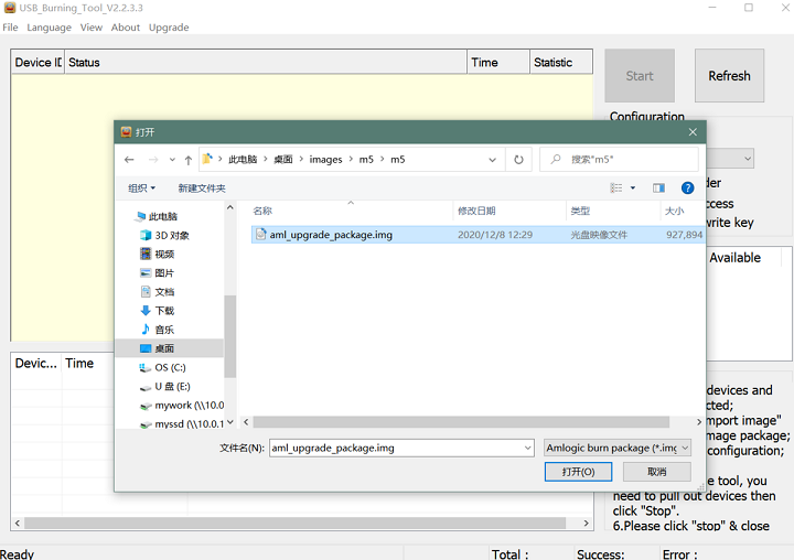
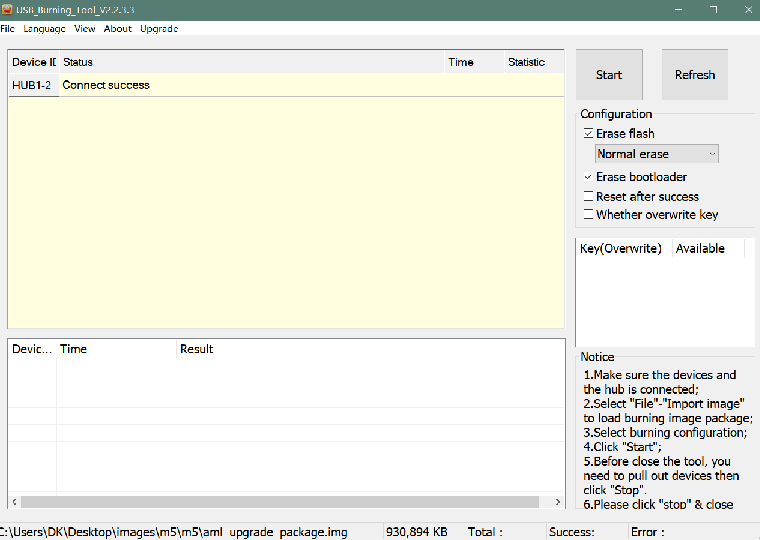
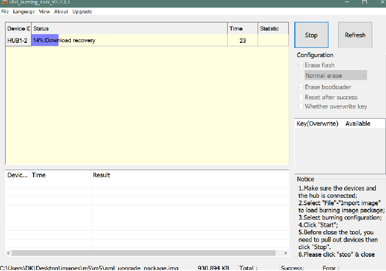
- 1. Open USB_Burning_Tool.exe, select menu File->Import image, choose the android image file aml_upgrade_package.img.
- 2. M5 board disconnect power, press and hold SW4 button beside 40pin header, plugin type-c usb cable to PC
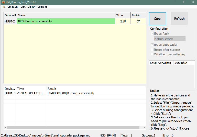
- 3. Click the Start button and wait for upgrade complete.
- 4. After Burning successfull, Unplug the type-c usb and connect to power supply adaptor to startup.
- 5. Click the Stop button to cancel the upgrade process and close the USB Buring Tool.
Build Android Source Code
- 1. Get Android 9.0 source code
$ git clone https://github.com/BPI-SINOVOIP/BPI-S905X3-Android9
- 2. Build the Android 9.0 Source code
- Please read the source code README.md
Linux
Prepare
- 1. Linux image support SDcard or EMMC bootup, but you should read the boot sequence at first.
- 2. Make sure bootable EMMC is formatted from sector 0 if you want bootup from SDcard, and make sure bootable SDcard is formatted if you want bootup from EMMC(because uboot read bootscript file from mmc:1 first, which is SDcard dev, This is used for quickly SDcard bootup debug or flash image to EMMC while EMMC is bootable).
- 3. Install bpi-tools on your Linux PC. If you can't access this URL or any other install problem, please go to bpi-tools source repo, download and install this tools manually.
 $ apt-get install pv
 $ curl -sL https://github.com/BPI-SINOVOIP/bpi-tools/raw/master/bpi-tools | sudo -E bash
- 4. Download Linux latest image.
- 5. Default login: pi/bananapi or root/bananapi
Install Image to SDcard
- 1. Install image with bpi-tools on Linux, plug SDcard to Linux PC and run
$ sudo bpi-copy xxx-bpi-m5-xxx.img.zip /dev/sdX
- 2. Install bpi image with Etcher on Windows, Linux and MacOS.
- Balena Etcher is an opensource project by Balena, Flash OS images to SDcard and USB drive
Install Image to EMMC
- 1. Prepare a SDcard with Linux image flashed and bootup board with this SDcard.
- 2. Copy Linux image to udisk, plug the udisk to board and mount it.
- 3. Install with bpi-tools command
$ sudo bpi-copy xxx-bpi-m5-xxx.img.zip /dev/mmcblk0
- 4. Install with dd command, umount mmcblk0p1 and mmcblk0p2 partition if mounted automatically.
 $ sudo apt-get install pv
 $ sudo unzip -p xxx-bpi-m5-xxx.img.zip | pv | dd of=/dev/mmcblk1 bs=10M status=noxfer
- 5. After download complete, power off safely and eject the SDcard.
Build Linux Source Code
- 1. Get the Linux bsp source code
$ git clone https://github.com/BPI-SINOVOIP/BPI-M5-bsp
- 2. Build the bsp source code
- Please read the source code README.md
- 3. If you want build uboot and kernel separately, please download the u-boot the kernel only, get the toolchains and configuration from BPI-M5-bsp
DTB overlay
- 1. DTB overlay is used for 40pin gpios multi-function configuration and install in vfat BPI-BOOT/overlays
 root@bananapi:~# ls /media/pi/BPI-BOOT/overlays/
 custom_ir.dtbo      pwm_b-backlight.dtbo  spi0.dtbo
 ds3231.dtbo         pwm_c-beeper.dtbo     uart1_cts_rts.dtbo
 hifi_pcm5102a.dtbo  pwm_cd-c.dtbo         uart1.dtbo
 hifi_pcm5122.dtbo   pwm_cd.dtbo           uart2.dtbo
 i2c0.dtbo           pwm_ef.dtbo           waveshare_tft24_lcd.dtbo
 i2c1.dtbo           pwm_ef-f.dtbo         waveshare_tft35c_lcd.dtbo
 pwm_ab.dtbo         sdio.dtbo             waveshare_tft35c_rtp.dtbo
- 2. Update the overlays env in vfat BPI-BOOT/boot.ini to enable what you want. Default i2c0, spi0 and uart1 enabled.
 # Overlays to load
 # Example combinations:
 #   spi0 i2c0 i2c1 uart0
 #   hktft32
 #   hktft35
 setenv overlays "i2c0 spi0 uart1"
- 3. Must be restart the board for overlay dtb loaded.
WiringPi
- Note: This WiringPi only support set 40pin gpio to output, input or software pwm, for io functions as i2c, spi, pwm..., you must enable dtb overlay in boot.ini
- 1. Build and install wiringPi
 $ git clone https://github.com/BPI-SINOVOIP/amlogic-wiringPi
 $ cd amlogic-wiringPi
 $ chmod a+x build
 $ sudo ./build
- 2. Run gpio readall to show all 40pins status.
root@bananapi:~/amlogic-wiringPi# gpio readall
+-----+-----+---------+------+---+--- M5 ---+---+------+---------+-----+-----+
| I/O | wPi |   Name  | Mode | V | Physical | V | Mode |  Name   | wPi | I/O |
+-----+-----+---------+------+---+----++----+---+------+---------+-----+-----+
|     |     |    3.3V |      |   |  1 || 2  |   |      | 5V      |     |     |
| 493 |   8 |   SDA.2 | ALT1 | 1 |  3 || 4  |   |      | 5V      |     |     |
| 494 |   9 |   SCL.2 | ALT1 | 1 |  5 || 6  |   |      | 0V      |     |     |
| 481 |   7 |  IO.481 |   IN | 1 |  7 || 8  | 1 | ALT1 | TxD1    | 15  | 488 |
|     |     |      0V |      |   |  9 || 10 | 1 | ALT1 | RxD1    | 16  | 489 |
| 479 |   0 |  IO.479 |   IN | 1 | 11 || 12 | 1 | IN   | IO.504  | 1   | 504 |
| 480 |   2 |  IO.480 |   IN | 1 | 13 || 14 |   |      | 0V      |     |     |
| 483 |   3 |  IO.483 |   IN | 1 | 15 || 16 | 1 | IN   | IO.476  | 4   | 476 |
|     |     |    3.3V |      |   | 17 || 18 | 1 | IN   | IO.477  | 5   | 477 |
| 484 |  12 |    MOSI | ALT4 | 1 | 19 || 20 |   |      | 0V      |     |     |
| 485 |  13 |    MISO | ALT4 | 1 | 21 || 22 | 1 | IN   | IO.478  | 6   | 478 |
| 487 |  14 |    SLCK | ALT4 | 1 | 23 || 24 | 1 | OUT  | SS      | 10  | 486 |
|     |     |      0V |      |   | 25 || 26 | 1 | IN   | IO.492  | 11  | 492 |
| 474 |  30 |   SDA.3 |   IN | 1 | 27 || 28 | 1 | IN   | SCL.3   | 31  | 475 |
| 490 |  21 |  IO.490 |   IN | 1 | 29 || 30 |   |      | 0V      |     |     |
| 491 |  22 |  IO.491 |   IN | 1 | 31 || 32 | 0 | IN   | IO.495  | 26  | 495 |
| 482 |  23 |  IO.482 |   IN | 0 | 33 || 34 |   |      | 0V      |     |     |
| 503 |  24 |  IO.503 |   IN | 1 | 35 || 36 | 0 | IN   | IO.432  | 27  | 432 |
| 505 |  25 |  IO.505 |   IN | 0 | 37 || 38 | 1 | ALT4 | IO.506  | 28  | 506 |
|     |     |      0V |      |   | 39 || 40 | 0 | IN   | IO.500  | 29  | 500 |
+-----+-----+---------+------+---+----++----+---+------+---------+-----+-----+
| I/O | wPi |   Name  | Mode | V | Physical | V | Mode |  Name   | wPi | I/O |
+-----+-----+---------+------+---+--- M5 ---+---+------+---------+-----+-----+
- 3. BPI GPIO Extend board and examples in amlogic-wiringPi/examples
- blinkall, blink all pin header gpios, no extend board.
- lcd-bpi, BPI LCD 1602 display module example.
- 52pi-bpi, BPI OLED Display Module example.
- matrixled-bpi, BPI RGB LED Matrix Expansion Module example.
- berryclip-bpi, BPI BerryClip Module
