Getting Started with M64
Contents
[hide]- 1 Introduction
- 2 Development For Android
Introduction
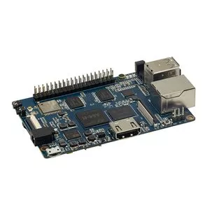
Banana Pi BPI-M64 is a 64-bit quad-core mini single board computer. It features 2GB of RAM and 8GB eMMC. It also has onboard WiFi and BT. On the ports side, the BPI-M64 has 2 USB A 2.0 ports, 1 USB OTG port, 1 HDMI port, 1 audio jack, and lastly a DC power port. The processor is pin-to-pin comptialbe with R18, so it comes with two versions:M64 and M64-R18
- Read more about : Banana Pi BPI-M64
A64 Key Features
- 1.2 Ghz Quad-Core ARM Cortex A53 64-Bit Processor-A64
- 2GB DDR3 SDRAM
- 8G EMMC
- 10/100/1000Mbps Ethernet
- WiFi (AP6212) & Bluetooth
R18 Key Features
- 1.2 Ghz Quad-Core ARM Cortex A53 64-Bit Processor-R18
- 2GB DDR3 SDRAM
- 8G EMMC
- 10/100/1000Mbps Ethernet
- WiFi (AP6212) & Bluetooth
Development For Android
Install Linux Image on M64
Prepare
 * Prepare 8G/above TF card, USB-Serial interface, PC with Ubuntu System
 * Using your USB-Serial Connect debug console on M64
Download Image to SDcard
 1.You could download latest image from our forum

 2.Install bpi-tools on your system
 * apt-get install pv
 * curl -sL https://github.com/BPI-SINOVOIP/bpi-tools/raw/master/bpi-tools | sudo -E bash

 3.After you download the image, insert your TF card into your Ubuntu
 * Execute "bpi-copy xxx.img /dev/sdx" to install image on your TF card.

 4.After step 3, then you can insert your TF card into M64, and press power button setup M64
Download Image to EMMC
 * Run your M64 with TF card
 * Copy "xxx-sd-emmc-xxx.img.zip / xxx-sd-emmc-xxx.img" to your USB disk
 * Plug your USB disk in M2U
 * After M64 recognise USB disk, execute "bpi-copy xxx-sd-emmc-xxx.img.zip / xxx-sd-emmc-xxx.img" to install image on EMMC
 * Then power off M64, take TF card out, power on M64
Switch to LCD7 bootup
- The default release images are HDMI bootup type, you can switch to LCD bootup type after first boot.
 $ sudo bpi-bootsel /usr/lib/u-boot/bananapi/bpi-m64/BPI-M64-LCD7-linux4.4-8k.img.gz
 $ reboot
Build M64 bsp source code
Other development and test
GMAC
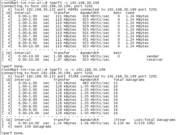
Use iperf3 to test gmac
1. On PC Terminal:
- Execute "iperf3 -s"
2. On M2U console:
- TCP test: "iperf3 -c serverIP"
- UDP test: "iperf3 -u -c serverIP"
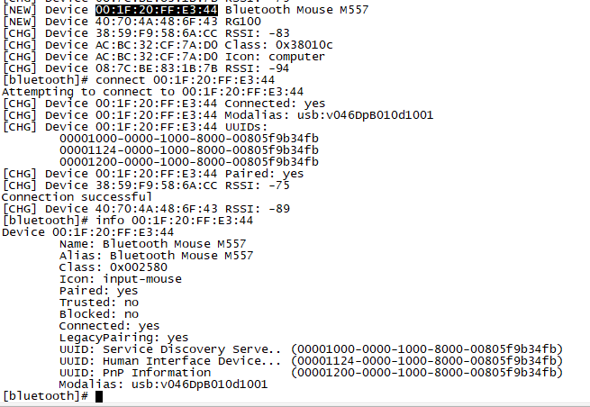
Bluetooth
- Use bluetoothctl tool to operate BT
- Execute "bluetoothctl"
- If you don't know how to use bluetoothctl, type "help", you will see more commands
- Execute these commands:
WiFi on A64
WiFi Client
You have two ways to setup WiFi Client
1. Use commands to setup WiFi client
- ip link set wlan0 up
- iw dev wlan0 scan | grep SSID
- vim /etc/wpasupplicant/wpa_supplicant.conf
 network={
 ssid="ssid"
 psk="password"
 priority=1
 }
- wpa_supplicant -iwlan0 -c /etc/wpa_supplicant/wpa_supplicant.conf
- dhclient wlan0
2. Use UI interface to setup WiFi Client
Ap Mode
1.Install hostapd and create hostapd configuration file hostapd.conf:
interface=wlan0
driver=nl80211
ssid=test
hw_mode=g
channel=1
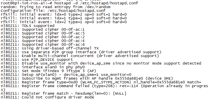
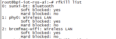
2.Execute command:"hostapd -d /<path>/hostapd.conf" If you meet problem like this:
Then, you could solve by following command:
- nmcli radio wifi off
- rfkill unblock 1
- rfkill unblock 2
- ifconfig wlan0 up
- hostapd -d hostapd.conf
Clear boot
- git clone https://github.com/BPI-SINOVOIP/BPI-files/tree/master/SD/100MB
- bpi-bootsel BPI-cleanboot-8k.img.gz /dev/sdX
GPIO Control
- To access a GPIO pin you first need to export it with
echo XX > /sys/class/gpio/export
- with XX being the number of the desired pin. To obtain the correct number you have to calculate it from the pin name (like PH18)
 (position of letter in alphabet - 1) * 32 + pin number
  for PH18 this would be ( 8 - 1) * 32 + 18 = 224 + 18 = 242 (since 'h' is the 8th letter)
- echo "out/in" > /sys/class/gpio/gpio*NUMBER*/direction
- echo "0/1" > /sys/class/gpio/gpio*NUMBER*/value
Camara function
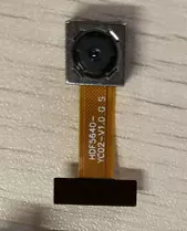
We use HDF5640 camara.
Guvcview
- Use your UI interface to operate camara
- Applications -> Sound & Video -> guvcview
Shell
- We also have built-in command in "/usr/local/bin" to test camara
- "./test_ov5640_image_mode.sh" to test picture taking function
- "./cameratest.sh" to test video recording function
IR function
- Execute "getevent"
- Use your IR device to send information to A64
RPi.GPIO
Install RPi.GPIO
- Execute "git clone https://github.com/BPI-SINOVOIP/RPi.GPIO"
- after clone the repo, cd RPi.GPIO
- Execute "sudo apt-get update"
- Execute "sudo apt-get install python-dev python3-dev"
- Execute "sudo python setup.py install" or "sudo python3 setup.py install" to install the module
Using RPi.GPIO
- cd /usr/local/bin
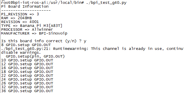
- Execute "./bpi_test_g40.py" to test RPi.GPIO
WringPi
- GitHub: https://github.com/BPI-SINOVOIP/BPI-WiringPi2.git
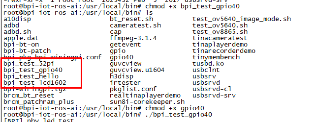
- We also have built-in test command in "/usr/local/bin"
How to Update WiringPi
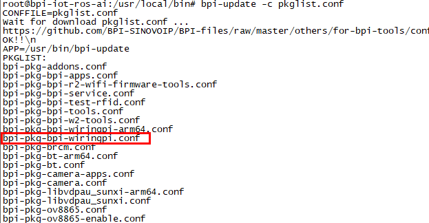
- Execute "bpi-update -c pkglist.conf"
- If your image is 32bit please do this command to install wring pi
- Execute "bpi-update -c bpi-pkg-bpi-wiringpi.conf"
- If your image is 64bit please do:"bpi-update -c bpi-pkg-bpi-wiringpi-arm64.conf"
RGB 1602 LCD
- Execute "/usr/local/bin/bpi_test_lcd1602.sh"
0.96 Inch OLED Display
- Execute "/usr/local/bin/bpi_test_52pi.sh"
8x8 RGB LED Martix
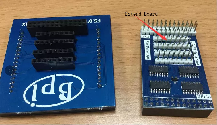
- Firstly you need a GPIO Extend Board for 8x8 LED Martix
- Execute "/usr/local/bin/bpi_test_gpio40.sh"
File System
- read only system change to read & write mode: "mount -o remount,rw /"
