Banana Pi BPI-M2 Berry
Contents
Introduction
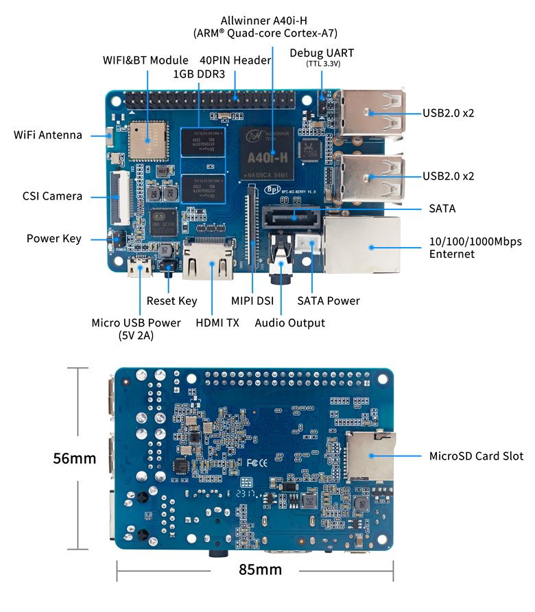
Banana Pi BPI-M2 Berry is a quad-core mini single board computer built with Allwinner V40 SoC. It features 1GB of RAM . It also has onboard WiFi and BT. On the ports side, the BPI-M2 Ultra has 4 USB A 2.0 ports, 1 USB OTG port, 1 HDMI port, 1 audio jack, a DC power port, and last but not least, a SATA port..
Also being a member of the Banana Pi family, the M2 Berry is a direct upgrade from the Banana Pi M1/M1+ that support SATA from the SoC. The SATA performance on the V40 is fitting for media related projects such as storage servers. Backed by our community, starting a project and building servers is fun and rewarding. We welcome all companies, DIYers, and tech loving people within our community! Together, we can make a difference, we can discover our passions, inspire others, and build a practical project.
all size is same as raspberry pi 3,so you can use raspberry pi 3 case for BPI-M2 Berry.
Key Features
- Allwinner R40/V40 Quad Core ARM Cortex A7 CPU
- 1GB DDR3 SDRAM.
- WiFi (AP6212) & Bluetooth onboard.
- SATA Interface.
- 4*USB 2.0
Getting Start
Hardware
Hardware interfact
Hardware spec
| HardWare Specification of Banana pi BPI-M2 Berry | |||
| Soc | Allwinner R40/V40 | ||
| CPU | quad-core cortex -A7,the most power efficient CPU core ARM's ever development | ||
| GPU | dual-core MALI-400 MP2 and runs at 500MHz, capable of 1.1 Gpixel/s throughput. Graphics capabilities are slightly higher than the original Xbox’s level of performance. The GPU provides OpenGL ES 2.0, hardware-accelerated OpenVG, 1080p45 H.264 high-profile encode and decode. | ||
| SDRAM | 1GB DDR3 with 733MHz\(shared with GPU\) | ||
| SATA | suppoort SATA interface | ||
| GPIO | 40 Pins Header, 28×GPIO, some of which can be used for specific functions including UART, I2C, SPI, PWM, I2S. | ||
| On board Network | 10/100/1000Mbps Ethernet \(Realtek RTL8211E/D\) | ||
| Wifi Module | WiFi 802.11 b/g/n \(AP 6212 module on board\) | ||
| Bluetooth | BT4.0 | ||
| On board Storage | MicroSD \(TF\) card,No eMMC onboard | ||
| Display | 4-lane MIPI DSI display,or RGB panel or LVDS panel,TV-out on HDMI V1.4 | ||
| Video | Multi-format FHD video decoding, including Mpeg1/2, Mpeg4, H.263, H.264, etc H.264 decode up to 1080P60,support video encodeing:High-deinition\(HD\)H.264 video encoder is up to 1080P@45fps | ||
| Audio outputs | HDMI, analog audio \(via 3.5 mm TRRS jack\), I2S audio \(also potentially for audio input\) | ||
| Camera | A CSI input connector Camera:Supports 8-bit YUV422 CMOS sensor interface,Supports CCIR656 protocol for NTSC and PAL,Supports 5M pixel camera sensor ,Supports video capture solution up to 1080p@30fps | ||
| Audio input | On board microphone | ||
| USB | 4 USB 2.0 host, 1 USB 2.0 OTG | ||
| Buttons | Reset button, Power button, U-boot button | ||
| Leds | Power status Led and RJ45 Led | ||
| IR | No onboard IR receiver | ||
| DC Power | 5V/2A with micro USB port | ||
| battery | No 3.7V lithium battery power support | ||
| Sizes | 85mmX56mm,same size as raspberry pi 3 | ||
| Weight | 40g | ||
GPIO PIN define
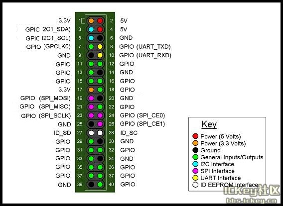
Banana Pi BPI-M2 Berry has a 40-pin GPIO header that matches that of the Model Raspberry Pi 3. Following is the Banana Pi GPIO Pinout:
| 40 PIN GPIO of Banana pi BPI-R2 | |||
| GPIO Pin Name | Default Function | Function2:GPIO | Function3 |
| CON1-P01 | VCC-3V3 | ||
| CON1-P02 | DCIN | ||
| CON1-P03 | TWI2-SDA | PB21 | PWM5 |
| CON1-P04 | DCIN | ||
| CON1-P05 | TWI2-SCK | PB20 | PWM4 |
| CON1-P06 | GND | ||
| CON1-P07 | PB3 | PB3 | PWM1 |
| CON1-P08 | UART2-TX | PI18 | SPI1\_MOSI |
| CON1-P09 | GND | ||
| CON1-P10 | UART2-RX | PI19 | SPI1\_MISO |
| CON1-P11 | UART7-TX | PI20 | PWM2 |
| CON1-P12 | UART2-CTS | PI17 | SPI1\_CLK |
| CON1-P13 | UART7-RX | PI21 | PWM3 |
| CON1-P14 | GND | ||
| CON1-P15 | PH25 | PH25 | CSI1-FIELD |
| CON1-P16 | UART2-RTS | PI16 | SPI1\_CS0 |
| CON1-P17 | VCC-3V3 | ||
| CON1-P18 | PH26 | PH26 | CSI1-HSYNC |
| CON1-P19 | SPI0\_MOSI | PC0 | |
| CON1-P20 | GND | ||
| CON1-P21 | SPI0\_MISO | PC1 | |
| CON1-P22 | PH27 | PH27 | CSI1-VSYNC |
| CON1-P23 | SPI0\_CLK | PC2 | |
| CON1-P24 | SPI0\_CS | PC23 | |
| CON1-P25 | GND | ||
| CON1-P26 | PH24 | PH24 | CSI1-PCLK |
| CON1-P27 | TWI3-SDA | PI1 | |
| CON1-P28 | TWI3-SCK | PI0 | |
| CON1-P29 | PH0 | PH0 | CSI1-D0 |
| CON1-P30 | GND | ||
| CON1-P31 | PH1 | PH1 | CSI1-D1 |
| CON1-P32 | PD20 | PD20 | CSI1-MCLK |
| CON1-P33 | PH2 | PH2 | CSI1-D2 |
| CON1-P34 | GND | ||
| CON1-P35 | PH3 | PH3 | CSI1-D3 |
| CON1-P36 | UART5-RX | PH7 | CSI1-D7 |
| CON1-P37 | UART4-TX | PH4 | CSI1-D4 |
| CON1-P38 | UART5-TX | PH6 | CSI1-D6 |
| CON1-P39 | GND | ||
| CON1-P40 | UART4-RX | PH5 | CSI1-D5 |
- CSI Camera Connector specification:**
The CSI Camera Connector is a 24-pin FPC connector which can connect external camera module with proper signal pin mappings. The pin definitions of the CSI interface are shown as below. This is marked on the Banana Pi board as “Camera”.
| CSI Pin Name | Default Function | Function2:GPIO | | :--- | :--- | :--- | | CN5-P01 | NC | | | CN5-P02 | GND | | | CN5-P03 | CSI0-SDA | PI3 | | | CN5-P04 | CSI0-AVDD | | CN5-P05 | CSI0-SCK | PI2 | | CN5-P06 | CSI0-Reset | PI7 | | CN5-P07 | CSI0-VSYNC | PE3 | | CN5-P08 | CSI0-PWDN | PI6 | | CN5-P09 | CSI0-HSYNC | PE2 | | | CN5-P10 | CSI0-DVDD | | | CN5-P11 | CSI0-DOVDD | | CN5-P12 | CSI0-D7 | PE11 | | CN5-P13 | CSI0-MCLK | PE1 | | CN5-P14 | CSI0-D6 | PE10 | | | CN5-P15 | GND | | CN5-P16 | CSI0-D5 | PE9 | | CN5-P17 | CSI0-PCLK | PE0 | | CN5-P18 | CSI0-D4 | PE8 | | CN5-P19 | CSI0-D0 | PE4 | | CN5-P20 | CSI0-D3 | PE7 | | CN5-P21 | CSI0-D1 | PE5 | | CN5-P22 | CSI0-D2 | PE6 | | CN5-P23 | GND | | | | CN5-P24 | CSI0-AFVCC |
- Display specification**
MIPI DSI \(Display Serial Interface\)
The display Connector is a 40-pin FPC connector which can connect external LCD panel \(MIPI DSI\) and touch screen \(I2C\) module as well. The pin definitions of this connector are shown as below. This is marked on the Banana Pi board as “DSI”.
| | DSI Pin Name | Default Function | Function2:GPIO | | :--- | :--- | :--- | :--- | | | | CN6-P01 | VCC-3V3 | | | | CN6-P02 | IPSOUT | | | | CN6-P03 | VCC-3V3 | | | CN6-P04 | IPSOUT | | | | | CN6-P05 | GND | | | | CN6-P06 | IPSOUT | | | | CN6-P07 | GND | | | | CN6-P08 | IPSOUT | | | | CN6-P09 | NC | | | | CN6-P10 | GND | | | | CN6-P11 | NC | | | | CN6-P12 | DSI-D0N | | | | CN6-P13 | NC | | | | CN6-P14 | DSI-D0P | | | | CN6-P15 | NC | | | | CN6-P16 | GND | | | CN6-P17 | TWI0-SDA | PB19 | | | | CN6-P18 | DSI-D1N | | | CN6-P19 | TWI0-SCK | PB18 | | | | CN6-P20 | DSI-D1P | | | CN6-P21 | CTP-INT | PI10 | | | CN6-P22 | GND | | | | CN6-P23 | CTP-RST | PI11 | | | CN6-P24 | DSI-CKN | | | | | CN6-P25 | GND | | | | CN6-P26 | DSI-CKP | | | CN6-P27 | LCD-BL-EN | PH16 | | | | CN6-P28 | GND | | | CN6-P29 | LCD-RST | PH17 | | | | CN6-P30 | DSI-D2N | | | CN6-P31 | LCD-PWR-EN | PH18 | | | | CN6-P32 | DSI-D2P | | | | CN6-P33 | GND | | | | CN6-P34 | GND | | | CN6-P35 | LCD-PWM | PB2 | | | | CN6-P36 | DSI-D3N | | | | CN6-P37 | GND | | | | CN6-P38 | DSI-D3P | | | | CN6-P39 | NC | | CN6-P40 | GND | | |
- UART specification:**
The header CON4 is the UART interface. For developers of Banana Pi, this is an easy way to get the UART console output to check the system status and log message.
| | CON2 Pin Name | Default Function | GPIO | | :--- | :--- | :--- | :--- | | | CON2 P03 | UART0-TXD | | | | CON2 P02 | UART0-RXD | | | CON2 P01 | GND | | |

