Banana Pi BPI-F3
BPI-F3 Introduction
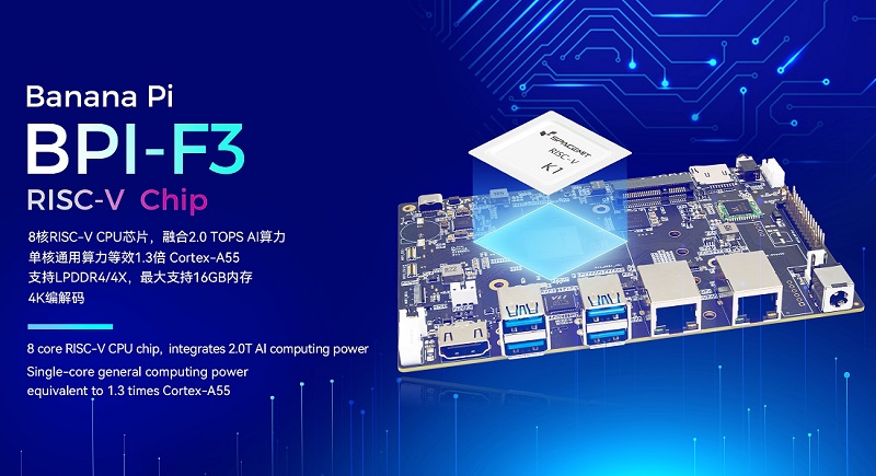
Banana Pi BPI-F3 is a industrial grade RISC-V development board, it design with SpacemiT K1 8 core RISC-V chip, CPU integrates 2.0 TOPs AI computing power. 8G DDR and 16G eMMC onboard.2x GbE Ethernet prot, 4x USB 3.0 and PCIe for M.2 interface, supprt HDMI and Dual MIPI-CSI Camera.
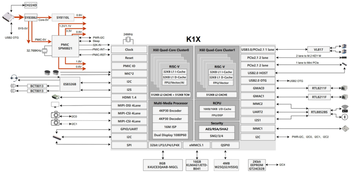
about SpacemiT K1 8 core RISC-V chip
SpacemiT K1 is an octa-core 64-bit RISC-V AI CPU. Base on RISC-V open instruction set architecture,we are committed to create more energy efficient and more commonly used AI processor platform,promote global open source and open ecological computing power construction.
SpacemiT K1 is mainly used for single board computer,network storage,cloud computer,smart robort,industrial control,edge computer,etc.
SpacemiT K1 8 core RISC-V chip Brief
SpacemiT K1 8 core RISC-V chip datasheet
Key Features
- 8 core RISC-V chip, CPU integrates 2.0 TOPs AI computing power
- Single-core general computing power equivalent to 1.3 times Cortex-A55
- Supports 32-bit LPDDR4/4X, with a maximum of 16GB of memory
- 4K decoding and encoding
- 5-lane PCIE2.1 expansion capability
- 1x USB 3.0 + 2x USB 2.0 interfaces
- 12x UART serial ports
- Operating temperature range: -40°C to 85°C
Application direction
- NAS
- Laptop
- Intelligent robotics
- Industrial control
- AI edge computing
Getting Start
Hardware
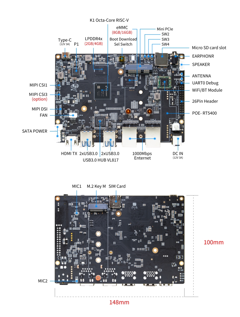
Hardware Interface
Hardware Spec
| HardWare Specification of Banana Pi BPI-F3 RISC-V SBC | |
| CPU | SpacemiT K1 8 core RISC-V chip |
| AI | 2.0Tops from RlSC-V Core |
| Memory | 4 GB LPDDR4 (Supports up to 8G LPDDR4) |
| Storage | 16G eMMC flash,4M SPI NOR,32M SPI NAD |
| SD card | MicroSD card slot (Greater than 256MB) |
| Wireless | 2.4G/5G WiFi and Bluetooth 4.2 |
| Ethernet | 2x GbE Ethernet port(supports PoE with add-on PoE HAT) |
| HDMI | 1x full-size HDMI digital Audio output(HDMI1.4,up to 1080p@60fps ) |
| Audio | Speaker,Mic, Earphone |
| Camera | MIPI-CSI, Dual-shot support |
| USB | 4x USB 3.0 Type-A HOST, 1x USB 2.0 Type-C OTG |
| PCIe | PCIE2.1 2lane * 2. |
| PCIEB 2lane connect M.2 KEY M( Support JMB582 expansion card to SATA ) | |
| PCIEC 1lane connect MINI PCIE | |
| GPIO | 26-pin header |
| Buttons | Reset, Power and Burn |
| IR | IR-Rx |
| LED | Power Status |
| Power | DC in and TYPE-C in |
| Size | 148x100 mm |
| Weight | 200g |
GPIO Pin Define
26 PIN GPIO
| 40-pin header define and GPIO Alternative Functions Assignments | |||
| PIN | Function | Function | PIN |
|---|---|---|---|
| 1 | VCC3V3_SYS | VCC5V0_OUT | 2 |
| 3 | AP_I2C4_SDA_3V3 | VCC5V0_OUT | 4 |
| 5 | AP_I2C4_SCL_3V3 | GND | 6 |
| 7 | GPIO_70_3V3 | R_UART0_TXD_3V3 | 8 |
| 9 | GND | R_UART0_RXD_3V3 | 10 |
| 11 | GPIO_71_3V3 | GPIO_74_3V3 | 12 |
| 13 | GPIO_72_3V3 | GND | 14 |
| 15 | GPIO_73_3V3 | GPIO_91_3V3 | 16 |
| 17 | VCC3V3_SYS | GPIO_92_3V3 | 18 |
| 19 | SPI3_MOSI_3V3 | GND | 20 |
| 21 | SPI3_MISO_3V3 | GPIO_49_3V3 | 22 |
| 23 | SPI3_SCLK_3V3 | SPI3_CS_3V3 | 24 |
| 25 | GND | GPIO_50_3V3 | 2 |
MIPI DSI screen connection socket
Holding a 1080P screen (JL-M101N013-P12WU-M402632), the screen socket model is FH35C-31S-0.3SHW (50)
| PIN | Function | Function | PIN |
|---|---|---|---|
| 1 | MIPI_DSI1_LANE0_DN | MIPI_DSI1_LANE0_DP | 2 |
| 3 | GND | MIPI_DSI1_LANE1_DN | 4 |
| 5 | MIPI_DSI1_LANE1_DP | GND | 6 |
| 7 | MIPI_DSI1_CLK_N | MIPI_DSI1_CLK_P | 8 |
| 9 | GND | MIPI_DSI1_LANE2_DN | 10 |
| 11 | MIPI_DSI1_LANE2_DP | GND | 12 |
| 13 | MIPI_DSI1_LANE3_DN | MIPI_DSI1_LANE3_DP | 14 |
| 15 | GND | MIPI_LCD_ADC_1V8 | 16 |
| 17 | LCD_PWR_EN_1V8 | LCD_RST_1V8 | 18 |
| 19 | LCD_BL_EN_1V8 | LCD_BL_PWM_1V8 | 20 |
| 21 | GND | TP_INT_1V8 | 22 |
| 23 | TP_RST_1V8 | AP_I2C6_SCL | 24 |
| 25 | AP_I2C6_SDA | LCD_VCC18 | 26 |
| 27 | GND | GND | 28 |
| 29 | LCD_VCC5V0 | LCD_VCC5V0 | 30 |
| 31 | LCD_VCC5V0 |
Camera module base
By default, it supports a 16M camera module, which can be modified After blocking the configuration, hold the 8M camera module and adopt a uniform spacing 0.4mm 30 pin socket (model QG1330421Y-M08-7H).
16M camera:
| PIN | Function | Function | PIN |
|---|---|---|---|
| 1 | GND | GND | 2 |
| 3 | GND | FS_DUALCAM | 4 |
| 5 | CAM_MCLK0 | GND | 6 |
| 7 | GND | CAMERA0_RST | 8 |
| 9 | MIPI_CSI1_DN0 | CAMERA0_PDN | 10 |
| 11 | MIPI_CSI1_DP0 | CAM_I2C0_SDA | 12 |
| 13 | GND | CAM_I2C0_SCL | 14 |
| 15 | MIPI_CSI1_CLKN | CSI_DVDD12 | 16 |
| 17 | MIPI_CSI1_CLKP | CSI_VCCIO18 | 18 |
| 19 | GND | GND | 20 |
| 21 | MIPI_CSI1_DN1 | CSI_AVDD28 | 22 |
| 23 | MIPI_CSI1_DP1 | CSI_AFVCC28 | 24 |
| 25 | GND | GND | 26 |
| 27 | MIPI_CSI1_DN2 | MIPI_CSI1_DP3 | 28 |
| 29 | MIPI_CSI1_DP2 | MIPI_CSI1_DN3 | 30 |
8M camera:
| PIN | Function | Function | PIN |
|---|---|---|---|
| 1 | MIPI_CSI3_DP3 | CAM_MCLK1 | 2 |
| 3 | MIPI_CSI3_DN3 | CAMERA1_RST | 4 |
| 5 | GND | CAMERA1_PDN | 6 |
| 7 | MIPI_CSI3_DP2 | GND | 8 |
| 9 | MIPI_CSI3_DN2 | CAM_I2C1_SDA | 10 |
| 11 | GND | CAM_I2C1_SCL | 12 |
| 13 | MIPI_CSI3_DP1 | GND | 14 |
| 15 | MIPI_CSI3_DN1 | CSI_VCCIO18 | 16 |
| 17 | GND | CSI_AVDD28 | 18 |
| 19 | MIPI_CSI3_CLKP | CSI_AFVCC28 | 20 |
| 21 | MIPI_CSI3_CLKN | CSI_DVDD12 | 22 |
| 23 | GND | FLASH_LED0+ | 24 |
| 25 | MIPI_CSI3_DP0 | FLASH_LED1+ | 26 |
| 27 | MIPI_CSI3_DN0 | GND | 28 |
| 29 | GND | GND | 30 |
POE support
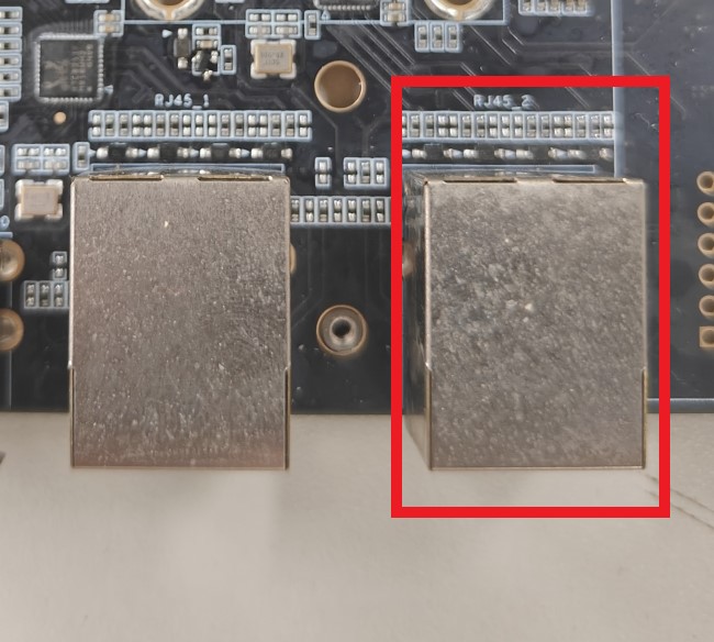
We design PoE function for BPI-R64 ,so easy to add PoE module to support PoE function.After welding the POE module, it is powered by the RJ45-2 interface.
4G module
After connecting to the MINI PCIE interface and inserting the SIM card, it can be used.
Development
Source Code
Linux BSP Source Code
Resources
- BPI-F3 run Ubuntu Linux test 8 Core CPU performance and AI function: https://www.youtube.com/watch?v=Ym-VcJgaGIY
- BPI-F3 SpacemiT K1 run OpenWRT: https://www.youtube.com/watch?v=ejV5KFww8Xo
- BPI-F3 run visual AI+ large models simultaneously: https://www.youtube.com/watch?v=Kn7GYiOxato
System Image
Tools
Linux
Bianbu
- Bianbu-23.10-nas-k1-v1.0rc1-release-20240429192450.img
- Baidu cloud: https://pan.baidu.com/s/1I1dkpOZXwS9AY8Ni-ZLYuw?pwd=8888 (pincode: 8888)
- Bianbu-23.10-desktop-k1-v1.0rc1-release-20240429194149.img
- Baidu cloud: https://pan.baidu.com/s/1IZgi9DCFnQ_AqsrpxFMMvg?pwd=8888 (pincode: 8888)
Armbian
- 2024-04-30-Armbian-unofficial_24.5.0-trunk_Bananapi-F3
- Baidu cloud: https://pan.baidu.com/s/1VIp3bwbDjMairyXXMZwNkQ?pwd=8888 (pincode: 8888)
Easy to buy
- SINOVOIP Aliexpress shop: https://www.aliexpress.com/item/3256806735430070.html
- BPI Aliexpress shop: https://www.aliexpress.com/item/3256806735645440.html
- Taobao Shop:https://item.taobao.com/item.htm?id=789483353026&spm=a213gs.v2success.0.0.220c4831vddhXz
- OEM&ODM,please contact: [email protected]


