BPI-UNO arduino UNO board
Contents
产品介绍
UNO是一个基于ATmega328P(数据手册)的微型开发板,它有14个数字输入/输出引脚(其中6个可以用作PWM输出),6个模拟输入,1个16MHZ的石英晶振,1个USB接口,1个ICSP接口和一个复位接口。它有着一个微型控制器所需的一切;只需通过USB将它插上电脑或者用电源适配器或者电池给它供电就可以马上开始你的编程之旅。使用UNO,你不必担心接错或者短路,就算短路你只需花十几块钱就可以替换上面的芯片并重新来
关键特征
- ATmega328P @16 MHz.
- 32 KB Flash.
- 2 KB SRAM.
- 1 KB EEPROM
硬件
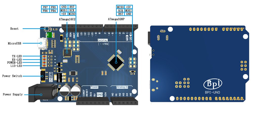
硬件接口示意
Hardware spec
| Banana Pi BP-UNO | |||
| Microcontroller | ATmega328P | ||
| Operating Voltage | 5V | ||
| Input Voltage: (recommended) | 7-12V | ||
| Input Voltage: (limits) | 6-20V | ||
| Digital I/O Pins | 14(include 6 PWM output) | ||
| PWM PIN | 6个 | ||
| Analog Input Pins | 6个 | ||
| I/O output Max | 20mA | ||
| 3.3V output Max | 50mA | ||
| Flash | 32KB(ATmega328P) and 0.5KB used by bootloader | ||
| SRAM | 2KB(ATmega328P) | ||
| EEPROM | 1KB(ATmega328P) | ||
| Clock Speed | 16MHz | ||
| onboard LED | 13 | ||
| size | same as arduino NANO | ||
There is a self-restoring fuse on the bpi-uno that automatically disconnects the power supply when short-circuiting or overcurrent exceeds 500mA, thus protecting the USB port and bpi-uno of the computer. While most computer USB ports provide internal protection, this fuse provides additional protection.
电源
可以通过USB口或者直流电源座给BPI-UNO供电。BPI-UNO带有自动切换电源功能。
电源引脚如下:
- Vin:电源输入引脚。当使用外部电源通过DC电源座供电时,这个引脚可以输出电源电压。
- 5V:5V电源引脚。使用USB供电时,直接输出USB提供的5V电压;使用外部电源供电时,输出稳压后的5V电压。
- 3V3:3.3V 电源引脚。最大输出能力为50 mA。
- GND:接地引脚
- IOREF:I/O参考电压。其他设备可通过该引脚识别开发板I/O参考电压。
输入输出
BPI-Uno有14个数字输入输出引脚,可使用 pinMode()、digitalWrite() 和 digitalRead() 控制。
其中一些带有特殊功能,这些引脚如下:
- Serial:0(RX)、1(TX),被用于接收和发送串口数据。这两个引脚通过连接到ATmega16u2来与计算机进行串口通信。
- 外部中断:2、3,可以输入外部中断信号。中断有四种触发模式:低电平触发、电平改变触发、上升沿触发、下降沿触发。
- PWM输出:3、5、6、9、10、11,可用于输出8-bit PWM波。对应函数 analogWrite() 。
- SPI:10(SS)、11(MOSI)、12(MISO)、13(SCK),可用于SPI通信。可以使用官方提供的SPI库操纵。
- L13:13号引脚连接了一个LED,当引脚输出高电平时打开LED,当引脚输出低电平时关闭LED。
- TWI:A4(SDA)、A5(SCL)和TWI接口,可用于TWI通信,兼容I²C通信。可以使用官方提供的Wire库操纵。
BPI-UNO 6个模拟输入引脚,可使用analogRead()读取模拟值。每个模拟输入都有10位分辨率(即1024个不同的值)。默认情况下,模拟输入电压范围为0~5V,可使用 AREF引脚和analogReference()函数设置其他参考电压。
相关引脚如下:
- AREF:模拟输入参考电压输入引脚。
- Reset:复位端口。接低电平会使BPI-UNO复位,复位按键按下时,会使该端口接到低电平,从而让BPI-UNO复位。
指示灯(LED)
BPI-UNO带有4个LED指示灯,作用分别如下:
- ON:电源指示灯。当BPI-UNO通电时,ON灯会点亮。
- TX:串口发送指示灯。当使用USB连接到计算机且BPI-UNO向计算机传输数据时,TX灯会点亮。
- RX:串口接收指示灯。当使用USB连接到计算机且BPI-UNO接收到计算机传来的数据时,RX灯会点亮。
- L13:可编程控制指示灯。该LED通过特殊电路连接到BPI-UNO的13号引脚,当13号引脚为高电平或高阻态时,该LED 会点亮;低电平时,不会点亮。可以通过程序或者外部输入信号,控制该LED亮灭。
通信
BPI-UNO具备多种通信接口,可以和计算机、其他BPI-UNO或者其他控制器通信。
ATmega328 提供了UART TTL (5V)串口通信,其位于0 (RX) 和1 (TX)两个引脚上。Uno上的ATmega16U2会在计算机上模拟出一个USB串口,使得ATmega328 能和计算机通信。Arduino IDE提供了串口监视器,使用它可以收发简单文本数据。Uno上的RX\TX两个LED可以指示当前Uno的通信状态。
SoftwareSerial库可以将Uno的任意数字引脚模拟成串口,从而进行串口通信。
ATmega328也支持I2C (TWI)和SPI通信。Arduino IDE自带的Wire库,可用于驱动I2C总线,自带的SPI库,可用于SPI通信。
自动复位
一些开发板在上传程序前需要手动复位,而BPI-UNO的设计不需要如此,在BPI-UNO连接电脑后可以由程序控制其复位。在ATmega16U2上的DTR信号端,经过一个100nf 的电容,连接到ATmega328 的复位引脚。
当计算机发出DTR信号时(低电平),复位端将得到一个足够长的脉冲信号,从而复位ATmega328。在Arduino IDE中点击上传程序,在上传前即会触发复位,从而运行引导程序,完成程序上传。
Arduino Software
Arduino IDE
You can program the PI-NANO through Arduino IDE。
On the BPI-Nano using ATmega328 chip, there is a bootloader program stored, allowing users to upload the program to the development board, without the need for additional programmers. The process of uploading the program was completed using the STK500 protocol.
You can also upload the program to bpi-uno via the ICSP interface without using bootloader
Arduino driver install
- 1,Windows10 :Windows10 Plug in BPI-Nano and the driver will be installed automatically
- 2,Windows7 :
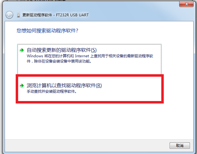
After plugging in bpi-uno, the system will try to install the driver automatically. If the installation fails, it will display, "failed to install the driver device successfully". In this case, the driver can be installed manually: Right click on "my computer", device manager, other devices; Right click on "unknown device" and click "update driver software" :
Select the second item, "browse the computer to find driver software";
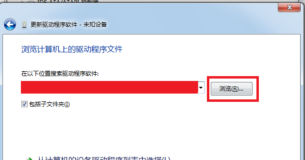
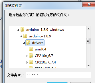
Click browse and select the driver address, which is the location of the driver in the ArduinoIDE you downloaded:
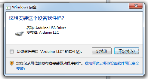
If the following prompt appears during installation, select "install" :
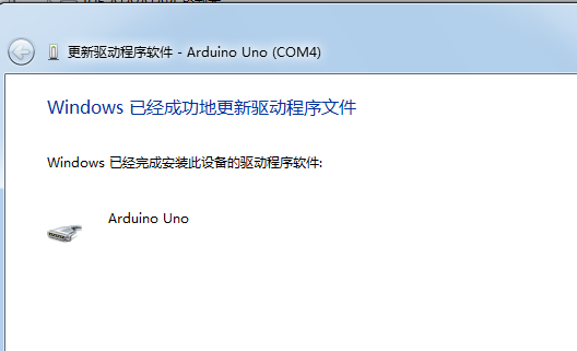
System prompt: driver installed successfully:
In the device manager, you can see the COM port for Arduino:
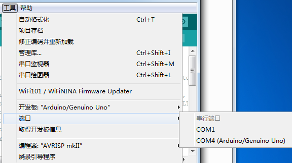
then you can find COM port in Arduino IDE
now, you can program with the Arudino IDE.
The resources
- Schematic diagram download :
- DXF file download:
