BPI NB-IoT Linaro 96Boars
BPI NB-IoT Linaro 96Boars with Quecte BC95 module developent board
Contents
Introduction
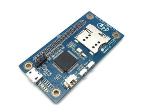
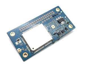
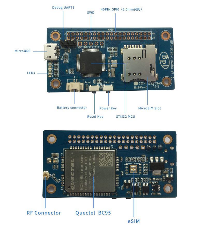
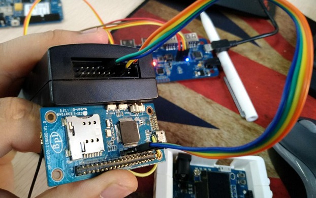
BPI NB-IoT Linaro 96Boars with BC95 module developent board ,this is banana pi team first board for Linaro 96Board standard development board.
1.NB-IoT module:
- NB-IoT module:Quectel BC95-B5/8/20 or BC95-G
- Model and Frequency band:
SIM card:
- Micro SD SIM Slot
- e-SIM optional(footprint reserved on the board)
- Antenna: IPEX antenna connector
2,MCU:
Hardware
Hardware inerface
Harware spec
| HardwareSpecification of BPi BC95-LINARO | |||
| Soc | STM32F103RBT6 | ||
| CPU | ARM 32-bit Cortex™-M3 CPU @72MHz | ||
| SDRAM size | 20 KB | ||
| Flash size | 128KB | ||
| Power | 5V/2A via MicroUSB / 2PIN Battery Connector | ||
| Low-level peripherals | 40 Pins Header \(2.0mm Pitch\), 32×GPIOs,Some of which can be used for specific functions including UART, I2C, SPI, PWM | ||
| On board Network | Quectel BC95 | ||
| On board SIM | MicroSD SIM SloteSIM\(option\) | ||
| USB | 1 USB 2.0 host | ||
| Buttons | Reset button, User button | ||
| Leds | 1 Power status Led and 5 other Leds | ||
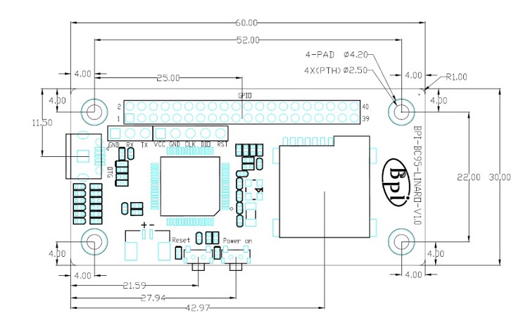
| Sizes | 60mm×30mm | ||
| Weight | 10g | ||
Dimensions
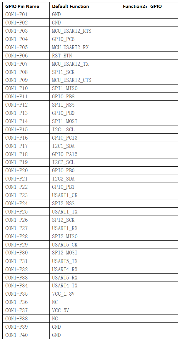
GPIO (CON1) define
40 PIN GPIO (CON1) define:
Software
Software introduction
1 ,Lite OS brief Huawei
LiteOS is a lightweight open-source IoT OS and a smart hardware development platform. It simplifies IoT device development and device connectivity, makes services smarter, delivers superb user experience, and provides better data protection. Huawei LiteOS is designed for smart homes, wearables, IoV, and intelligent manufacturing applications.
For more about HuaWei Lite OS please refer to:
http://developer.huawei.com/ict/en/site-iot/product/liteos
IDE:recommended development environment is MDK521 + STM32F1xxx library
2,BC95 software brief:
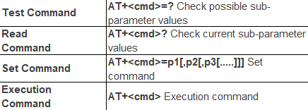
Command format:
- Searching network steps:
- AT+NBAND?//QueryBand
- AT+CFUN?//value :1
- AT+CIMI//Query IMSI number
- AT+CSQ/Query the signal strength
- AT+NUESTATS//Query module status
- AT+CGATT?//Back + CGATT: 1 indicates that the attachment is successful, with a delay of about 30s
- AT+CEREG?//Search for network status, 1 for Internet, 2 for Network
- AT+CSCON?//Query the connection status, 1 CONNECT, 0 IDLE
- Manually configure network if fails to register network automatically:
- AT+CFUN=1 AT+CIMI//Execute CFUN = 1, wait for 4 seconds to query IMSI, if it can be found that the card has been identified;If not, please check the card is inserted and confirm whether it is a USIM card.
- AT+NBAND?//Query frequency band information.
- AT+CEREG=1//Set to automatically register network registration status, when the module registered on the network, will report URC.**AT+CGDCONT=1,“IP”,“APN”**//The APN is configured locally \(or not configured\) for local access.
- AT+COPS=1,2,"46000"**//Specify PLMN search, PLMN configuration.
- AT+CSQ//Query signal strength.
- AT+NUESTATS// Query module status
- AT+CGATT?//Back + CGATT: 1 indicates that the attachment is successful, with a delay of about 30s
- AT+CEREG?//Search for network status, 1 for Internet, 2 for Network
- AT+CSCON?//Query the connection status, 1 CONNECT, 0 IDLE
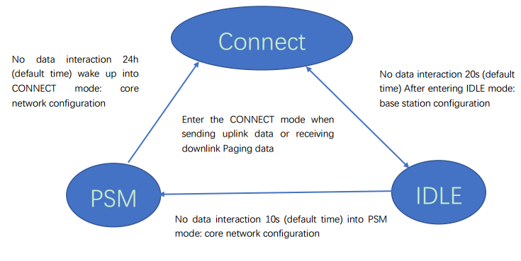
Network connectivity status chart:
1. Connect status \(+ CSCON: 0, 1, the module is in this state after network injection\), the duration of this state is configured by the base station, and from
From time to time to control the device, the range of 1-3600s, the default 20s.
1. Idle state \(+ CSCON: 0,0\), this state lasts the time to dispose by the key network, by Active timer \(T3324\) Come Control, the range of 0-11160s, the default 10s.
2. PSM state \(Judgment by power consumption, the maximum power consumption 5uA\), the duration of the state by the core network configuration, set by the TAU Timer \(T3412\) to control the range of 0h-310h, the default 24h.
How to setup and start to use
Hardware preparation
- BPI OPEN DEBUGGER or J-Link DEBUGGER *1
- BPI BC95-Linaro development board *1
- Micro USB cable *2*
- Dupont lines\(female female\)*4
Hardware hookup
There are two ways to flash by either BPI OPEN DEBUGGER or J-Link DEBUGGER:
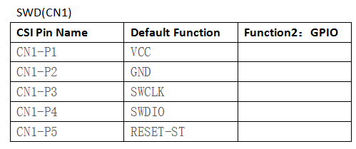
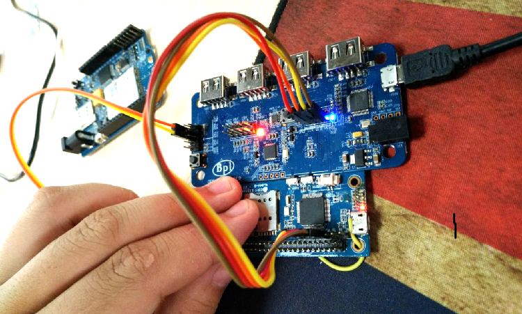
1.BPI OPEN DEBUGGER: Using Dupont lines to connect BPI OPEN DEBUGGER with BPI BC95-Linaro SWD port,the connection are below:
| connect way | |||
| BPI OPEN DEBUGGER | BPI NB-IoT Linaro SWD | ||
| 3V3 | VCC | ||
| GND | GND | ||
| DIO | DIO | ||
| CLK | CLK | ||
2.J-Link DEBUGGER:
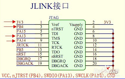
The corresponding connection between JLink and BPI BC95 are the following:
| connect way | |||
| J-link | BPI NB-IoT Linaro SWD | ||
| 3V3 \(Pin1\) | VCC | ||
| GND \(Pin4.6.8.10……\) | GND | ||
| SWDIO \(Pin7\) | DIO | ||
| SWCLK \(Pin9\) | CLK | ||
| nJTRST (Pin3)optional | RST \(optional\) | ||
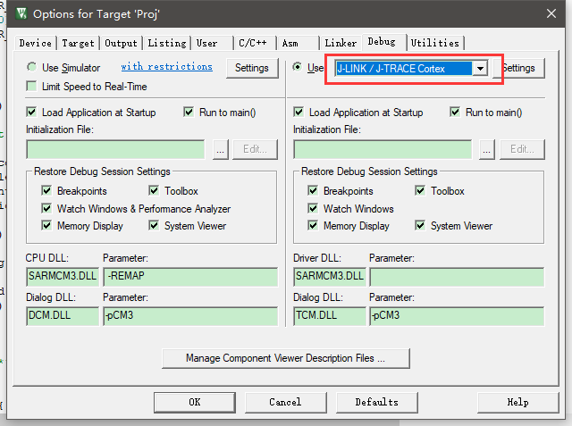
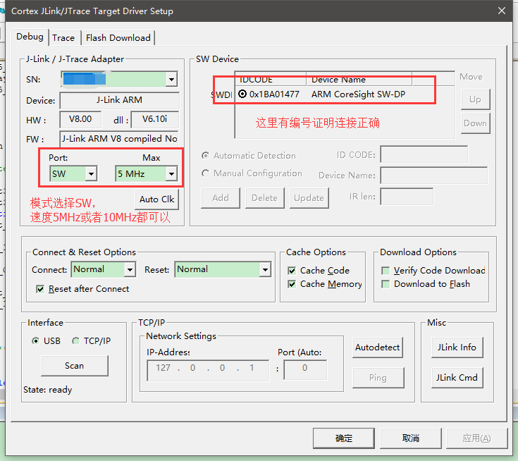
3.Software debugging setting:
MDK5 setting:
Create a project choosing the right chip,and set the Options of Target as follows:
4.Software sample cases:
There are two samples in BPI forum, please refer to the following links:
1.https://github.com/yelvlab/BPI_NB-IoT_Linaro_96Boards/tree/master/example/Debugger_USART
2.https://github.com/yelvlab/BPI_NB-IoT_Linaro_96Boards/tree/master/example/Debugger_Virtual_USB
3.Github code :https://github.com/yelvlab/BPI_NB-IoT_Linaro_96Boards
HUAWEI LiteOS:
BPI NB-Iot Linaro 96Boards Easy Development with Arduino
Let us see how you can setup the Banana Pi Linaro with your favourite Arduino IDE and Maple
- Step 1: Install the Arduino board for STM32
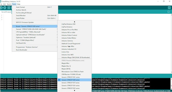
In order to use your board with the Arduino IDE, the first step is to install the board definition. Open your Arduino IDE. We tested this on 1.6.10
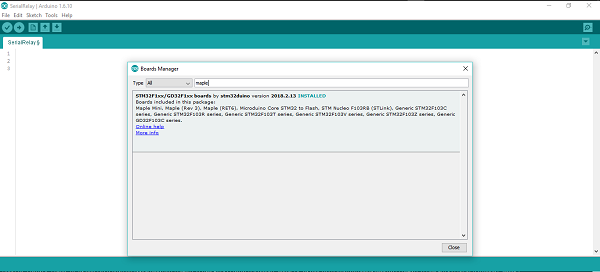
Go to Tools > Board > Board Manager
Search for 'Maple Mini' as shown below and install the STM32F1xx by stmduino board
When the board is installed, you will be able to see that there are few board definitions that are added as shown below.
Out of the newly installed boards, we are interested in the STM32F103R series, which is the tiny powerhouse we have in our Banana Pi. Like any other Arduino board you will also get the samples for the board under File >Examples >A_STM32_Examples
- Step 2: Install Maple bootloader on microcontroller
If you are lucky enough to get your hands on a Banana Pi with Maple bootloader, you can skip this step. Else read on..
In order to flash a firmware to a microcontroller, usually you need a dedicated programmer for this task such as a PiCKit for PIC microcontrollers and AVR ISP for Atmel AVR microcontrollers. However an easier option is to use a bootloader. A bootloader is a small piece of code that runs for few seconds when the microcontroller is started to check for new firmware over Serial or USB and writes the new firmware to the program memory if available. Arduino has many different bootloaders available for AtMega 328, AtMega 2560 chips by Atmel such as Uno, nano, Mega, Diecimilia etc. in their boards. This makes it very convenient to program a microcontroller right from the IDE (such as Arduino) since it does not need a programmer hardware. All this time you have played with your Arduino, you have been using Atmel chips with Arduino bootloaders programmed via the Arduino IDE. A programmer is needed only to flash the bootloader, which needs to be done only once.
The STM32F103 microcontroller we have in our Banana Pi has its own method of firmware update using a special protocol called DFU. Device Firmware Update (DFU) is a standard protocol used to flash firmware updates to devices over USB. Most middle to high end microcontrollers have in built DFU for conducting firmware updates. The STM microcontroller in our Banana Pi has DFU and in built USB which enables it to flash firmware very easily. This is different to how things are done in an Arduino board with a ATMEL microcontroller where a USB-Serial bridge (FTDI232, PL2303 etc.) connects the host PC USB with the microcontroller USART0. This is because the ATMega 328 or ATMega 2560 microcontrollers in standard Arduino Uno, Nano or Mega boards (except the Leonardo) do not have in built USB ports. Therefore once you plug in the Banana Pi to the PC, it should be detected as a DFU device since DFU device drivers usually comes with any modern Windows OS. We will show how it can be done in Ubuntu in a later post.
If what you read above sounded greek, fear not, as there is a easy way out. The maple bootloader enables you to use the STM just like an Arduino.To make an STM work with Arduino IDE with the board that we installed in the previous step, you should write the Maple bootloader to the STM which is a one time thing. You can find a good resource on how to install the Maple bootloader at Leaf Labs
http://docs.leaflabs.com/docs.leaflabs.com/index.html
You will need a STLink programmer for this process. Once the bootloader is flashed to the memory the DFU becomes active after a board reset for a short period for firmware update. If the IDE does not initiate a firmware update, the STM goes on to execute the program code. Now, the board will now be visible as a COM port in your PC just like an Arduino.
- Step 3: Setup Maple drivers on PC
Remember how we said that the board will be recognized as a DFU device by Windows? Most of the time you will need to introduce the drivers to the device in order to be recognized successfully. This is done using a simple tool called 'wdi-simple'. Refer this video
https://www.youtube.com/watch?v=0jdJp3TQuJY
for step by step instructions and this great github link
https://github.com/rogerclarkmelbourne/Arduino_STM32/wiki/Maple-drivers
for more info. Once the drivers are introduced properly, your Banana Pi will be fully functional for firmware update as well as Serial communication just like a our plain old Arduino Uno.
More information at
Resources
Source code
- HUAWEI LiteOS:
- LiteOS_Partner Development Kits:
- BPI github :
Documents
- BPI NB-Iot Linaro 96Boards Easy Development with Arduino
- Quecte BC95 datasheet (CN version)
- STM32F103(LD) datasheet.
- Discuss on forum :
- Easy to buy sample:
