Banana Pi BPI-ZERO
Introduction
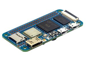
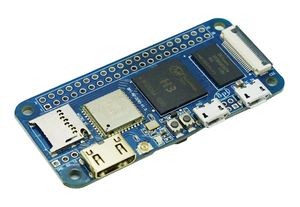
Banana Pi M2 Zero is an ultra compact single board computer measures only 60mm*30mm. It uses quad-core Cortex A7 allwinner H2+ processor, with 512MB RAM memory. It's ideal for light-weight systems with some space-limited applications. Like other members of Banana Pi, it supports both linux and android operating system.
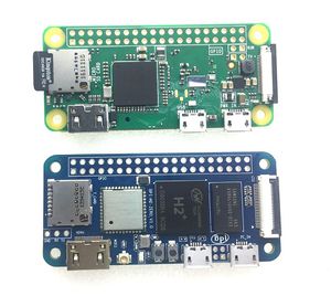
mini size only 60mm*30mm, all interface same as Raspberry pi Zero W.
Key Features
- CPU: Allwinner H2+, Quad-core Cortex-A7.
- 512MB DDR 3 SDRAM.
- WiFi (AP6212) & Bluetooth onboard.
- Mini HDMI.
- 40 PIN GPIO,It includes UART, SPI, I2C, IO etc
Getting Start
- Quick strart your BPI-M2 zero Quick Start Banana pi SBC
Hardware
Hardware interfact
Hardware spec
| HardWare Specification of Banana pi BPI-M2 zero | |||
| CPU | H2+ Quad-core Cortex-A7 H265/HEVC 1080P | ||
| GPU | Mali400MP2 GPU @600MHz,Supports OpenGL ES 2.0 | ||
| Memory \(SDRAM\) | 512M \(shared with GPU\) | ||
| Onboard Storage | TF card \(Max. 64GB\) | ||
| Onboard Network | NOPE | ||
| Onboard WIFI | SDIO AP6212(option AP6181、AP6335) | ||
| Video Input | A CSI input connector Camera:1 Supports 8-bit YUV422 CMOS sensor interface,2 Supports CCIR656 protocol for NTSC and PAL,3 Supports SM pixel camera sensor ,4 Supports video capture solution up to 1080p@30fps | ||
| Video Outputs | Supports Mini HDMI Port | ||
| Audio Output | Mini HDMI | ||
| Power Source | Micro USB with 5V/2A | ||
| USB 2.0 Ports | one USB 2.0 OTG | ||
| Buttons | Power Button, Reset Button | ||
| Low-level peripherals | 40 Pins Header,compatible with Raspberry Pi 3 | ||
| uart GPIO\(1x3\) pin | UART, ground | ||
| LED | Power led & Status led | ||
| IR | nope | ||
| Supported OS | Android, Ubuntu, Debian, Rasberry Pi Image | ||
| Product size | 65mm × 30mm | ||
| Weight | 35g | ||
GPIO PIN define
Banana Pi BPI-M2 zero has a 40-pin GPIO header that matches that of the Model Raspberry Pi 3. Following is the Banana Pi GPIO Pinout:
| 40 PIN GPIO of Banana pi BPI-R2 | |||
| GPIO Pin Name | Default Function | Function2:GPIO | Function3 |
| CON2-P01 | VCC-3V3 | ||
| CON2-P02 | VCC-5V | ||
| CON2-P03 | TWI0-SDA | PA12-EINT12 | |
| CON2-P04 | VCC-5V | ||
| CON2-P05 | TWI0-SCK | PA11-EINT11 | |
| CON2-P06 | GND | ||
| CON2-P07 | PWM1 | PA6-EINT6 | |
| CON2-P08 | UART3-TX | PA13-EINT13 | SPI1-CS |
| CON2-P09 | GND | ||
| CON2-P10 | UART3-RX | PA14-EINT14 | SPI1-CLK |
| CON2-P11 | UART2-RX | PA1-EINT1 | |
| CON2-P12 | UART3-CTS | PA16-EINT16 | SPI1-MISO |
| CON2-P13 | UART2-TX | PA0-EINT0 | |
| CON2-P14 | GND | ||
| CON2-P15 | UART2-CTS | PA3-EINT3 | |
| CON2-P16 | UART3-RTS | PA15-EINT15 | SPI1-MOSI |
| CON2-P17 | VCC-3V3 | ||
| CON2-P18 | PC4 | PC4 | |
| CON2-P19 | SPI0-MOSI | PC0 | |
| CON2-P20 | GND | ||
| CON2-P21 | SPI0-MISO | PC1 | |
| CON2-P22 | UART2-RTS | PA2-EINT2 | |
| CON2-P23 | SPI0-CLK | PC2 | |
| CON2-P24 | SPI0-CS | PC3 | |
| CON2-P25 | GND | ||
| CON2-P26 | PC7 | PC7 | |
| CON2-P27 | TWI1-SDA | PA19-EINT19 | |
| CON2-P28 | TWI1-SCK | PA18-EINT18 | |
| CON2-P29 | PA7-EINT7 | PA7-EINT7 | |
| CON2-P30 | GND | ||
| CON2-P31 | PA8-EINT8 | PA8-EINT8 | |
| CON2-P32 | PL2-S-EINT2 | PL2-S-EINT2 | |
| CON2-P33 | PA9-EINT9 | PA9-EINT9 | |
| CON2-P34 | GND | ||
| CON2-P35 | PA10-EINT10 | PA10-EINT10 | |
| CON2-P36 | PL4-S-EINT4 | PL4-S-EINT4 | |
| CON2-P37 | PA17-EINT17 | PA17-EINT17 | SPDIF-OUT |
| CON2-P38 | PA21-EINT21 | PA21-EINT21 | |
| CON2-P39 | GND | ||
| CON2-P40 | PA20-EINT20 | PA20-EINT20 | |
CSI Camera Connector specification:
The CSI Camera Connector is a 24-pin FPC connector which can connect external camera module with proper signal pin mappings. The pin definitions of the CSI interface are shown as below. This is marked on the Banana Pi board as “CSI″.
| 24 PIN CSI Camera connector of Banana pi BPI-R2 | |||
| CSI Pin Name | Default Function | Function2:GPIO | |
| CN3-P01 | NC | ||
| CN3-P02 | GND | ||
| CN3-P03 | CSI0-SDA | PE13 | |
| CN3-P04 | CSI0-AVDD | ||
| CN3-P05 | CSI0-SCK | PE12 | |
| CN3-P06 | CSI0-Reset | PE14 | |
| CN3-P07 | CSI0-VSYNC | PE3 | |
| CN3-P08 | CSI0-PWDN | PE15 | |
| CN3-P09 | CSI0-HSYNC | PE2 | |
| CN3-P10 | CSI0-DVDD | ||
| CN3-P11 | CSI0-DOVDD | ||
| CN3-P12 | CSI0-D7 | PE11 | |
| CN3-P13 | CSI0-MCLK | PE1 | |
| CN3-P14 | CSI0-D6 | PE10 | |
| CN3-P15 | GND | ||
| CN3-P16 | CSI0-D5 | PE9 | |
| CN3-P17 | CSI0-PCLK | PE0 | |
| CN3-P18 | CSI0-D4 | PE8 | |
| CN3-P19 | CSI0-D0 | PE4 | |
| CN3-P20 | CSI0-D3 | PE7 | |
| CN3-P21 | CSI0-D1 | PE5 | |
| CN3-P22 | CSI0-D2 | PE6 | |
| CN3-P23 | GND | ||
| CN3-P24 | CSI0-DOVDD | ||
UART specification:
The jumper CON3 is the UART interface. For developers of Banana Pi, this is an easy way to get the UART console output to check the system status and log message.
| jumper CON3 of Banana pi BPI-R2 | |||
| CON3 Pin Name | Default Function | GPIO | |
| CON3 P03 | UART0-TXD | PA4 | |
| CON3 P02 | UART0-RXD | PA5 | |
| CON3 P01 | GND | ||
Software
Android
Linux
Opnewrt
Development
Basic Development
how to use zero 10/100 Ethernet
Zero power with GPIO 5V input
Resources
Documents
- schematic diagram: https://drive.google.com/file/d/0B4PAo2nW2KfnMW5sVkxWSW9qa28/view?usp=sharing
- DXF file :https://drive.google.com/file/d/0B4PAo2nW2KfnZGcycVk2bWhmWjA/view?usp=sharing
- CE FCC RoHS : BPI-M2 zero CE,FCC,RoHS
- Allwinner documents:
- allwinner H3 chip doc baidu link: https://pan.baidu.com/s/1qTULll2CR02d0Hw9itq1rw
- Allwinner H2+ chip doc baidu link: https://pan.baidu.com/s/1TGMYr3rhizfhlg5hl6hLyg
- Banana Pi M2 Zero - Review and compare to RPI Zero:https://www.youtube.com/watch?v=CaXi1qbOvYk
Source code
- Android 4.4 source code
Image Release
Android 4.4
- 2017-11-12 update Android 4.4
- Google Drive:https://drive.google.com/open?id=1TywrMLLxqJj23ql2jyzLruZw18V_XwX3
- Baidu Cloud : https://pan.baidu.com/s/1c2pTXUo
- MD5: 67a5953dac47f3ca7a2628e1422a36e2
- Forum pthread:
- http://forum.banana-pi.org/t/bpi-m2-zero-new-image-android-4-4-version-v1/4384
Armbian
- Image Link:
- Forum thread:
RetroPie
- RetroPie for Banana Pi M2 Zero v.1.2.1 beta
Ubuntu 16.04 mate desktop 2017-11-13
- Image Link:
- Forum thread:


