Difference between revisions of "BPI NB-IoT Linaro 96Boars"
(→How to setup and start to use) |
(→How to setup and start to use) |
||
| Line 179: | Line 179: | ||
|- | |- | ||
|} | |} | ||
| + | |||
| + | 3.Software debugging setting: | ||
| + | |||
| + | MDK5 setting: | ||
| + | |||
| + | Create a project choosing the right chip,and set the Options of Target as follows: | ||
| + | |||
| + | [[File:Quectel_9.png]] | ||
| + | |||
| + | [[File:Quectel_10.jpg]] | ||
=Resources= | =Resources= | ||
Revision as of 04:32, 8 May 2018
BPI NB-IoT Linaro 96Boars with Quecte BC95 module developent board
Contents
Introduction
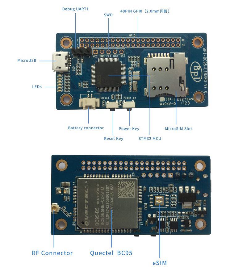
BPI NB-IoT Linaro 96Boars with BC95 module developent board ,this is banana pi team first board for Linaro 96Board standard development board.
1.NB-IoT module:
- NB-IoT module:Quectel BC95-B5/8/20 or BC95-G
- Model and Frequency band:
SIM card:
- Micro SD SIM Slot
- e-SIM optional(footprint reserved on the board)
- Antenna: IPEX antenna connector
2,MCU:
Hardware
Hardware inerface
Harware spec
| HardwareSpecification of BPi BC95-LINARO | |||
| Soc | STM32F103RBT6 | ||
| CPU | ARM 32-bit Cortex™-M3 CPU @72MHz | ||
| SDRAM size | 20 KB | ||
| Flash size | 128KB | ||
| Power | 5V/2A via MicroUSB / 2PIN Battery Connector | ||
| Low-level peripherals | 40 Pins Header \(2.0mm Pitch\), 32×GPIOs,Some of which can be used for specific functions including UART, I2C, SPI, PWM | ||
| On board Network | Quectel BC95 | ||
| On board SIM | MicroSD SIM SloteSIM\(option\) | ||
| USB | 1 USB 2.0 host | ||
| Buttons | Reset button, User button | ||
| Leds | 1 Power status Led and 5 other Leds | ||
| Sizes | 60mm×30mm | ||
| Weight | 10g | ||
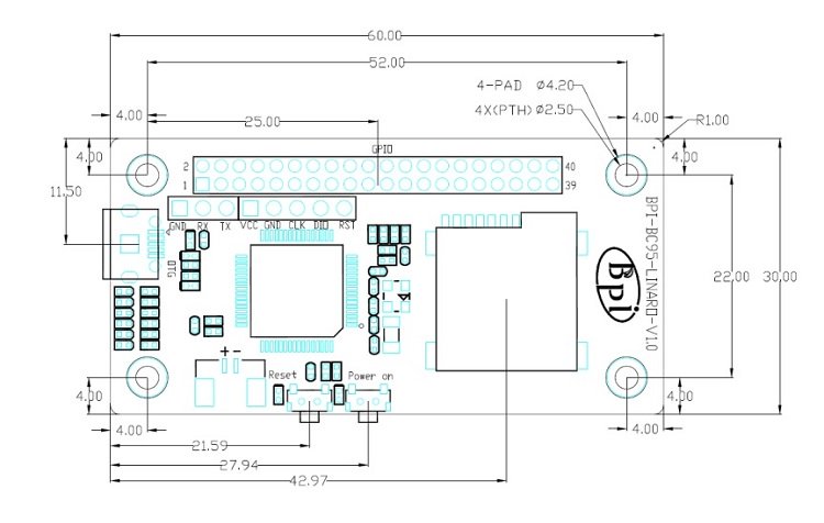
Dimensions
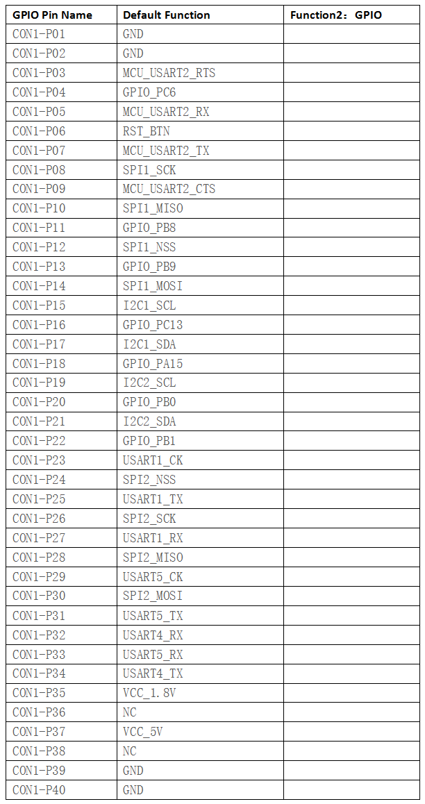
GPIO (CON1) define
40 PIN GPIO (CON1) define:
Software
Software introduction
1 ,Lite OS brief Huawei
LiteOS is a lightweight open-source IoT OS and a smart hardware development platform. It simplifies IoT device development and device connectivity, makes services smarter, delivers superb user experience, and provides better data protection. Huawei LiteOS is designed for smart homes, wearables, IoV, and intelligent manufacturing applications.
For more about HuaWei Lite OS please refer to:
http://developer.huawei.com/ict/en/site-iot/product/liteos
IDE:recommended development environment is MDK521 + STM32F1xxx library
2,BC95 software brief:
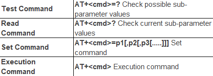
Command format:
- Searching network steps:
- AT+NBAND?//QueryBand
- AT+CFUN?//value :1
- AT+CIMI//Query IMSI number
- AT+CSQ/Query the signal strength
- AT+NUESTATS//Query module status
- AT+CGATT?//Back + CGATT: 1 indicates that the attachment is successful, with a delay of about 30s
- AT+CEREG?//Search for network status, 1 for Internet, 2 for Network
- AT+CSCON?//Query the connection status, 1 CONNECT, 0 IDLE
- Manually configure network if fails to register network automatically:
- AT+CFUN=1 AT+CIMI//Execute CFUN = 1, wait for 4 seconds to query IMSI, if it can be found that the card has been identified;If not, please check the card is inserted and confirm whether it is a USIM card.
- AT+NBAND?//Query frequency band information.
- AT+CEREG=1//Set to automatically register network registration status, when the module registered on the network, will report URC.**AT+CGDCONT=1,“IP”,“APN”**//The APN is configured locally \(or not configured\) for local access.
- AT+COPS=1,2,"46000"**//Specify PLMN search, PLMN configuration.
- AT+CSQ//Query signal strength.
- AT+NUESTATS// Query module status
- AT+CGATT?//Back + CGATT: 1 indicates that the attachment is successful, with a delay of about 30s
- AT+CEREG?//Search for network status, 1 for Internet, 2 for Network
- AT+CSCON?//Query the connection status, 1 CONNECT, 0 IDLE
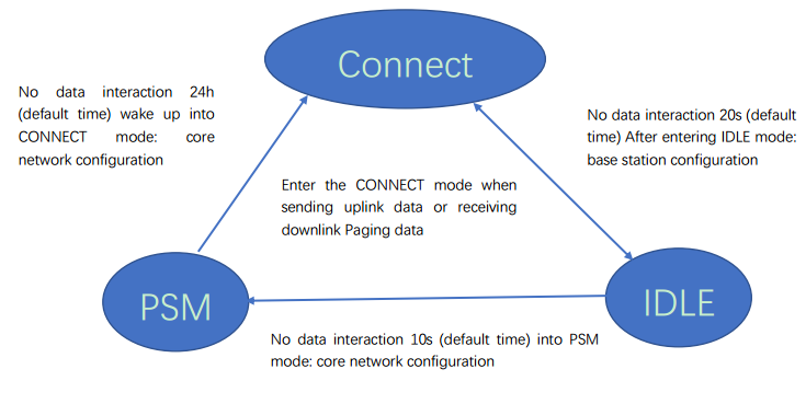
Network connectivity status chart:
1. Connect status \(+ CSCON: 0, 1, the module is in this state after network injection\), the duration of this state is configured by the base station, and from
From time to time to control the device, the range of 1-3600s, the default 20s.
1. Idle state \(+ CSCON: 0,0\), this state lasts the time to dispose by the key network, by Active timer \(T3324\) Come Control, the range of 0-11160s, the default 10s.
2. PSM state \(Judgment by power consumption, the maximum power consumption 5uA\), the duration of the state by the core network configuration, set by the TAU Timer \(T3412\) to control the range of 0h-310h, the default 24h.
How to setup and start to use
Hardware preparation
- BPI OPEN DEBUGGER or J-Link DEBUGGER *1
- BPI BC95-Linaro development board *1
- Micro USB cable *2*
- Dupont lines\(female female\)*4
Hardware hookup
There are two ways to flash by either BPI OPEN DEBUGGER or J-Link DEBUGGER:
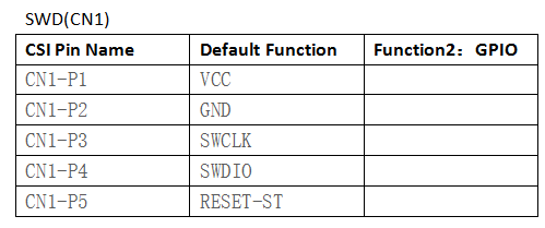
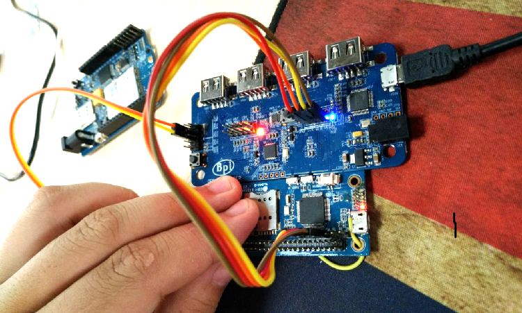
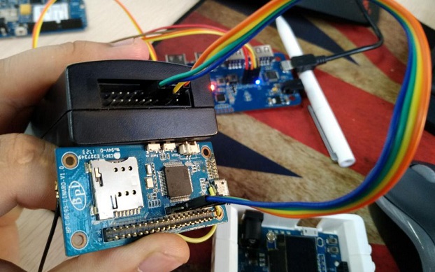
1.BPI OPEN DEBUGGER: Using Dupont lines to connect BPI OPEN DEBUGGER with BPI BC95-Linaro SWD port,the connection are below:
| connect way | |||
| BPI OPEN DEBUGGER | BPI NB-IoT Linaro SWD | ||
| 3V3 | VCC | ||
| GND | GND | ||
| DIO | DIO | ||
| CLK | CLK | ||
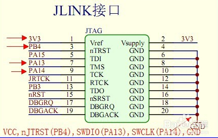
2.J-Link DEBUGGER:
The corresponding connection between JLink and BPI BC95 are the following:
| connect way | |||
| J-link | BPI NB-IoT Linaro SWD | ||
| 3V3 \(Pin1\) | VCC | ||
| GND \(Pin4.6.8.10……\) | GND | ||
| SWDIO \(Pin7\) | DIO | ||
| SWCLK \(Pin9\) | CLK | ||
| nJTRST (Pin3)optional | RST \(optional\) | ||
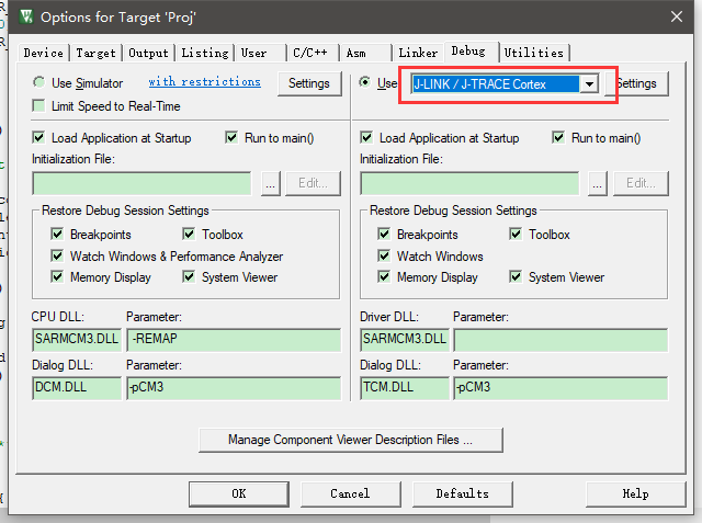
3.Software debugging setting:
MDK5 setting:
Create a project choosing the right chip,and set the Options of Target as follows:
Resources
Quecte BC95 datasheet (CN version) https://drive.google.com/file/d/0B4PAo2nW2KfnWnRVczZXV3lPZmc/view?usp=sharing
STM32F103(LD) datasheet.
EN: https://drive.google.com/file/d/0B4PAo2nW2KfnUm1na2tSOXQzNzg/view?usp=sharing
CN: https://drive.google.com/file/d/0B4PAo2nW2KfneUdMMzktLVNZSlU/view?usp=sharing
Discuss on forum : http://forum.banana-pi.org/t/bpi-nb-iot-linaro-96boars-with-quecte-bc95-module-developent-board/3416/2


