Difference between revisions of "Banana Pi BPI-M4 Berry"
(→Hardware interface) |
|||
| Line 1: | Line 1: | ||
[[zh:香蕉派_BPI-M4_Berry]] | [[zh:香蕉派_BPI-M4_Berry]] | ||
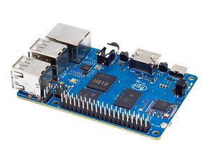
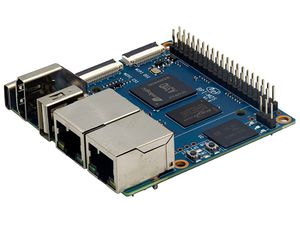
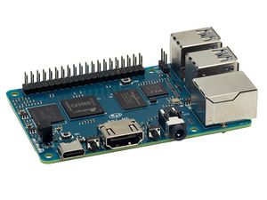
| − | [[File:Banana_Pi_BPI-M4_Berry_1.jpg|thumb|[[Banana Pi BPI-M4 Berry]] | + | [[File:Banana_Pi_BPI-M4_Berry_1.jpg|thumb|[[Banana Pi BPI-M4 Berry]] H618 design]] |
[[File:Banana_pi_BPI-M2_Berry_5.JPG|thumb|[[Banana Pi BPI-M2 Berry]] A40i-H design]] | [[File:Banana_pi_BPI-M2_Berry_5.JPG|thumb|[[Banana Pi BPI-M2 Berry]] A40i-H design]] | ||
Revision as of 00:36, 27 September 2023
Contents
Introduction
The BPI-M4 Berry development board stands as a powerful Single Board Computer (SBC), harnessing the capabilities of the Allwinner H618 System-on-Chip (SoC) to provide developers with impressive performance and a wealth of features. Similar to the Raspberry Pi 4b, the BPI-M4 Berry boasts comparable CPU prowess, LPDDR4 memory support, integrated WiFi and Bluetooth functionalities, and a familiar 40-pin header layout, alongside 4 USB interfaces and a GbE RJ45 port.
Characterized by its robust performance, versatile features, and remarkable image processing capabilities, stands as an exemplary SBC development platform for professionals within the embedded and computing industries. Equipped with 8GB eMMC flash storage, high-performance decoding and encoding capabilities, and an array of interface options, it caters to a wide spectrum of application domains, including media processing, IoT, and entertainment. Whether catering to novices or seasoned developers, the BPI-M4 Berry development board offers an ideal toolset for realizing creative visions and project objectives.
Key Features
- Allwinner H618, Quad-core ARM Cortex™-A53 processor
- ARM Mali G31 GPU
- WIFI & Bluetooth
- 2G LPDDR4 RAM
- 8G eMMC flash memory
- 1x USB2.0 Type-C OTG, 5V power supply
- 4x USB2.0 Type-A
- 1x HDMI 2.0a
- 1x 3.5mm Audio & TVE jack socket
- 1x GbE Ethernet port
Getting Start
Hardware
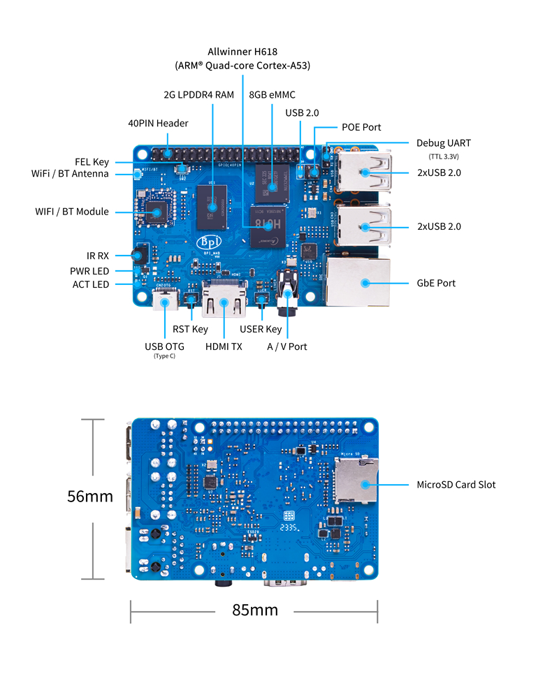
Hardware interface
Hardware spec
| Hardware Specification of Banana pi BPI-M4 Berry | |
| CPU | Allwinner H618, Quad-core ARM Cortex™-A53 processor, 64-bit, up to 1.5GHz |
| GPU | ARM Mali G31 GPU |
| Memory | 2 GB LPDDR4 |
| Storage | 8G eMMC flash |
| SD card | MicroSD card slot |
| Wireless | 2.4G/5G WiFi and Bluetooth 4.2 |
| Ethernet | 1x GbE Ethernet port(supports PoE with add-on PoE HAT) |
| HDMI | 1x full-size HDMI 2.0a (up to 4K@60Hz with HDR10, CEC, DDC, SCDC), HDMI digital Audio output |
| Audio | 1x 3.5mm Audio & TVE jack socket |
| IR | 1x CIR |
| USB | 4x USB2.0 Type-A HOST, 1x USB2.0 Type-C OTG |
| GPIO | 40-pin header, 28 pins GPIO and Power (+5V, +3.3V and GND) |
| UART, SPI, TWI/I²C, PWM, PCM/I²S | |
| Buttons | Reset, FEL and User |
| LED | Power Status and Activity status |
| Power | 5V@3A via USB Type-C |
| Size | 85x56 mm |
| Weight | |
BPI-M4 Berry VS Raspberry Pi 4b
PIN define
BPI-M4 Berry 40-pin header
| 40-pin header define and GPIO Alternative Functions Assignments | |||||
| Pin Num | Pin Name | ALT0 | ALT1 | ALT2 | ALT3 |
|---|---|---|---|---|---|
| 1 | 3.3V | ||||
| 2 | 5V | ||||
| 3 | PG16 | UART2_RX | TWI4_SDA | ||
| 4 | 5V | ||||
| 5 | PG15 | UART2_TX | TWI4_SCK | ||
| 6 | GND | ||||
| 7 | PG19 | PWM1 | |||
| 8 | PG6 | UART1_TX | |||
| 9 | GND | ||||
| 10 | PG7 | UART1_RX | |||
| 11 | PH2 | UART5_TX | PWM2 | ||
| 12 | PG11 | H_I2S2_BCLK | |||
| 13 | PH3 | UART5_RX | PWM1 | ||
| 14 | GND | ||||
| 15 | PG2 | ||||
| 16 | PG8 | UART1_RTS | |||
| 17 | 3.3V | ||||
| 18 | PG9 | UART1_CTS | |||
| 19 | PH7 | UART2_RTS | H_I2S3_LRCK | SPI1_MOSI | |
| 20 | GND | ||||
| 21 | PH8 | UART2_CTS | H_I2S3_DOUT0 | SPI1_MISO | H_I2S3_DIN1 |
| 22 | PG1 | ||||
| 23 | PH6 | UART2_RX | H_I2S3_BCLK | SPI1_CLK | |
| 24 | PH5 | UART2_TX | H_I2S3_MCLK | SPI1_CS0 | |
| 25 | GND | ||||
| 26 | PH9 | H_I2S3_DIN0 | SPI1_CS1 | H_I2S3_DOUT1 | |
| 27 | PG18 | UART2_CTS | TWI3_SDA | ||
| 28 | PG17 | UART2_RTS | TWI3_SCK | ||
| 29 | PG3 | ||||
| 30 | GND | ||||
| 31 | PG4 | ||||
| 32 | PG0 | ||||
| 33 | PG5 | ||||
| 34 | GND | ||||
| 35 | PG12 | H_I2S2_LRCK | |||
| 36 | PH4 | ||||
| 37 | PG10 | H_I2S2_MCLK | |||
| 38 | PG14 | H_I2S2_DIN0 | H_I2S2_DOUT1 | ||
| 39 | GND | ||||
| 40 | PG13 | H_I2S2_DOUT0 | H_I2S2_DIN1 | ||
BPI-M4 Berry Debug UART
| 1 | GND | |
| 2 | PH1 | UART0_RX |
| 3 | PH0 | UART0_TX |
