快速上手 M2 Zero: Difference between revisions
Jump to navigation
Jump to search
JackZengWiki (talk | contribs) |
JackZengWiki (talk | contribs) |
||
| Line 17: | Line 17: | ||
* Mini HDMI. | * Mini HDMI. | ||
= | =开发= | ||
== | ==基础开发== | ||
=== | ===开发前的准备=== | ||
* | * 准备一张容量至少 8Gb 的TF卡, 串口线, 一台运行Ubuntu系统的PC机 | ||
* | * 使用串口线连接M2 Zero的调试串口 | ||
[[Image:Debug_console_wire.png]] | [[Image:Debug_console_wire.png]] | ||
| Line 27: | Line 27: | ||
[[Image:M2_Zero_debug_console.png]] | [[Image:M2_Zero_debug_console.png]] | ||
=== | ===烧录第一个Linux镜像到 M2 Zero=== | ||
1. | 1.你可以从下面链接下载最近的镜像 | ||
* Here is the example: http://forum.banana-pi.org/t/bananapi-bpi-m2z-h2-new-image-raspbian-ubuntu-release-2018-07-09/6221 | * Here is the example: http://forum.banana-pi.org/t/bananapi-bpi-m2z-h2-new-image-raspbian-ubuntu-release-2018-07-09/6221 | ||
2. | 2.在你的Ubuntu系统电脑上安装bpi-tools, 执行以下命令即可安装: | ||
* apt-get install pv | * apt-get install pv | ||
* curl -sL https://github.com/BPI-SINOVOIP/bpi-tools/raw/master/bpi-tools | sudo -E bash | * curl -sL https://github.com/BPI-SINOVOIP/bpi-tools/raw/master/bpi-tools | sudo -E bash | ||
3. | 3.下载完镜像后, 插入TF卡到你的Ubuntu电脑中 | ||
* | * 运行命令 "bpi-copy xxx.img /dev/sdx" 烧录镜像到你的TF卡中. | ||
4. | 4.烧录完成后, 把TF卡插到M1中, 按住M1的电源键启动M1. | ||
=== | ===如何更新你的镜像=== | ||
1. | 1.运行下面命令下载 M2 Zero 的代码: https://github.com/BPI-SINOVOIP/BPI-M2Z-bsp | ||
* git clone https://github.com/BPI-SINOVOIP/BPI-M2Z-bsp | * git clone https://github.com/BPI-SINOVOIP/BPI-M2Z-bsp | ||
2. | 2.运行下面命令编译代码 | ||
* ./build.sh BPI-M2Z-720P | * ./build.sh BPI-M2Z-720P | ||
3. | 3.编译完成后, 执行命令 "cd SD", 然后将你已经烧录过系统的TF卡插到Ubuntu系统的电脑上, 执行 "fdisk -l" 来确认你的sd卡被识别为那个驱动盘了, 如:/dev/sdX. | ||
4. | 4.运行命令 "bpi-update -c bpi-r2.conf -d /dev/sdX", 来更新编译后的内核到你的 TF 卡中. | ||
== | ==深入开发== | ||
=== | ===如何生成一个镜像=== | ||
* | * 准备一张已经烧录系统的sd卡(Ubuntu/Raspbian/..) | ||
* | * 将sd卡插入到M2 Zero中并启动, 拷贝你需要的文件或者驱动到系统中, 然后关机M2 Zero. [如果你不需要拷贝文件或者驱动, 则可以跳过这一步] | ||
* | * 将你的sd卡插到运行Ubuntu系统的PC机中, 执行命令 "cd /media", then "ln -s <your account> pi" | ||
* | * 执行命令 "bpi-migrate -c bpi-m2z.conf -c ubuntu-mate-from-sd.conf -d /dev/sdx" 开始制作镜像 | ||
* | * 命令执行完成后, 你的镜像就生成了 | ||
=== | ===OTG接口=== | ||
1. | 1. 启动 adb 调试 | ||
* | * M2 Zero启动后,执行命令 "./adbd.sh" | ||
* 运行命令 "ps -ax | grep adbd" 观察adb进程是否已经启动 | |||
* 如果adbd成功启动, 用usb-otg线连接 M2 Zero和运行Ubuntu系统的PC机 | |||
* 在PC机上运行命令 "adb devices" 来观察PC机是否已经识别到 M2 Zero 的 OTG接口了 | |||
* 如果识别到了再执行命令 "adb shell" 来通过adb连接M2 Zero | |||
===USB 有线网络=== | |||
* 准备一根USB 转 OTG 线, 一个usb转网口的适配器 | |||
===USB | |||
* | |||
[[Image:M2Zero_usb_network_wire.png]] | [[Image:M2Zero_usb_network_wire.png]] | ||
* | * 使用 iperf3 来测试网络 | ||
[[Image:M2Zero_network.png]] | [[Image:M2Zero_network.png]] | ||
=== | ===蓝牙=== | ||
* | * 使用 bluetoothctl 命令来操作蓝牙 | ||
* | * 执行命令 "bluetoothctl" | ||
* | * 如果你知道怎么使用 bluetoothctl, 可以输入 "help" 命令, 执行help后你可以看到更多命令 | ||
* | * 执行以下命令: | ||
[[Image:M2Zero_bluetooth.png]] | [[Image:M2Zero_bluetooth.png]] | ||
===WiFi | ===WiFi 功能=== | ||
''' | '''这里提供两种方法来开启WiFi''' | ||
1. | 1. 使用命令行来开启WiFi | ||
* ip link set wlan0 up | * ip link set wlan0 up | ||
* iw dev wlan0 scan | grep SSID | * iw dev wlan0 scan | grep SSID | ||
| Line 95: | Line 94: | ||
* dhclient wlan0 | * dhclient wlan0 | ||
2. | 2. 使用图形界面来开启WiFi | ||
=== | ===清除 boot=== | ||
1. 执行以下命令来清除boot | |||
* git clone https://github.com/BPI-SINOVOIP/BPI-files/tree/master/SD/100MB | * git clone https://github.com/BPI-SINOVOIP/BPI-files/tree/master/SD/100MB | ||
* bpi-bootsel BPI-cleanboot-8k.img.gz /dev/sdX | * bpi-bootsel BPI-cleanboot-8k.img.gz /dev/sdX | ||
=== | ===摄像头功能=== | ||
这里使用 HDF5640 摄像头为例子. | |||
[[Image:ov5640_camara.png]] | [[Image:ov5640_camara.png]] | ||
==== | ====使用Guvcview==== | ||
* | * 使用图形界面来操作摄像头 | ||
* Applications -> Sound & Video -> guvcview | * Applications -> Sound & Video -> guvcview | ||
==== | ====使用Shell==== | ||
* | * 使用我们提供的集成到 /usr/local/bin 的命令来测试摄像头 | ||
* "./test_ov5640_image_mode.sh" | * "./test_ov5640_image_mode.sh" 测试拍照功能 | ||
* "./cameratest.sh" | * "./cameratest.sh" 测试摄像功能 | ||
===BPI | ===BPI 工具=== | ||
==== | ====安装BPI 工具==== | ||
* | 1. 执行下面命令来安装BPI 命令工具 | ||
* "curl -sL https://github.com/BPI-SINOVOIP/bpi-tools/raw/master/bpi-tools | sudo -E bash - " | |||
==== | ====更新 BPI 工具==== | ||
* | * 执行命令 "bpi-tools" 即可更新 | ||
[[Image: Bpi-tools.png]] | [[Image: Bpi-tools.png]] | ||
===RPi.GPIO=== | ===RPi.GPIO=== | ||
==== | ====安装 RPi.GPIO==== | ||
* | * 执行命令 "git clone https://github.com/BPI-SINOVOIP/RPi.GPIO" | ||
* | * 克隆代码后, 进入到 "cd RPi,GPIO" | ||
* | * 执行命令 "sudo apt-get update" | ||
* | * 执行命令 "sudo apt-get install python-dev python3-dev" | ||
* | * 执行命令 "sudo python setup.py install" or "sudo python3 setup.py install" to install the module | ||
==== | ====使用 RPi.GPIO==== | ||
* cd /usr/local/bin | * cd /usr/local/bin | ||
* | * 执行命令 "./bpi_test_g40.py" 可以测试Rpi.GPIO | ||
[[Image: RPi_GPIO.png]] | [[Image: RPi_GPIO.png]] | ||
| Line 137: | Line 138: | ||
===WiringPi=== | ===WiringPi=== | ||
* GitHub: https://github.com/BPI-SINOVOIP/BPI-WiringPi2.git | * GitHub: https://github.com/BPI-SINOVOIP/BPI-WiringPi2.git | ||
* | * 我们提供了集成的命令在 "/usr/local/bin" 中 | ||
==== | ====如何更新 WiringPi==== | ||
* | * 执行命令 "bpi-update -c pkglist.conf" | ||
[[Image: Update_Pkglist.png]] | [[Image: Update_Pkglist.png]] | ||
* | * 执行命令 "bpi-update -c bpi-pkg-bpi-wiringpi.conf" | ||
[[Image: Update_WringPi.png]] | [[Image: Update_WringPi.png]] | ||
====RGB 1602 LCD==== | ====RGB 1602 LCD==== | ||
* | * 执行命令 "/usr/local/bin/bpi_test_lcd1602.sh" | ||
====0.96 Inch OLED Display==== | ====0.96 Inch OLED Display==== | ||
* | * 执行命令 "/usr/local/bin/bpi_test_52pi.sh" | ||
====8x8 RGB LED Martix==== | ====8x8 RGB LED Martix==== | ||
* | * 首先你需要一个8x8 LED Martix 的 GPIO 扩展板 | ||
[[Image: WringPi_LED_Martix_Extend_Board.png]] | [[Image: WringPi_LED_Martix_Extend_Board.png]] | ||
* | * 执行命令 "/usr/local/bin/bpi_test_gpio40.sh" | ||
Revision as of 07:34, 12 October 2018
介绍


- 关于更多 : Banana Pi BPI-ZERO
BPI-M2 Zero
香蕉派 M2 Zero 是一种超小型单板电脑,量度仅为60mm×30mm, 其搭载了4核 Cortex A7架构的 allwinner芯片 H2+, 外加512Mb内存. 其适用于空间有限的轻量级系统, 像香蕉派的其他开发板一样,它支持Linux和Android操作系统。
关键特性
- Quad Core ARM Cortex A7 CPU H2+
- 512MB SDRAM.
- WiFi (AP6212) & Bluetooth .
- Mini HDMI.
开发
基础开发
开发前的准备
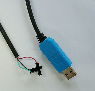
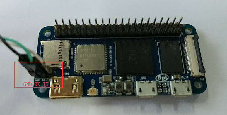
 * 准备一张容量至少 8Gb 的TF卡, 串口线, 一台运行Ubuntu系统的PC机
 * 使用串口线连接M2 Zero的调试串口


烧录第一个Linux镜像到 M2 Zero
 1.你可以从下面链接下载最近的镜像
 * Here is the example: http://forum.banana-pi.org/t/bananapi-bpi-m2z-h2-new-image-raspbian-ubuntu-release-2018-07-09/6221

 2.在你的Ubuntu系统电脑上安装bpi-tools, 执行以下命令即可安装:
 * apt-get install pv
 * curl -sL https://github.com/BPI-SINOVOIP/bpi-tools/raw/master/bpi-tools | sudo -E bash

 3.下载完镜像后, 插入TF卡到你的Ubuntu电脑中
 * 运行命令 "bpi-copy xxx.img /dev/sdx" 烧录镜像到你的TF卡中.

 4.烧录完成后, 把TF卡插到M1中, 按住M1的电源键启动M1.
如何更新你的镜像
 1.运行下面命令下载 M2 Zero 的代码: https://github.com/BPI-SINOVOIP/BPI-M2Z-bsp
 * git clone https://github.com/BPI-SINOVOIP/BPI-M2Z-bsp
 2.运行下面命令编译代码
 * ./build.sh BPI-M2Z-720P
 3.编译完成后, 执行命令 "cd SD", 然后将你已经烧录过系统的TF卡插到Ubuntu系统的电脑上, 执行 "fdisk -l" 来确认你的sd卡被识别为那个驱动盘了, 如:/dev/sdX.

 4.运行命令 "bpi-update -c bpi-r2.conf -d /dev/sdX", 来更新编译后的内核到你的 TF 卡中.
深入开发
如何生成一个镜像
- 准备一张已经烧录系统的sd卡(Ubuntu/Raspbian/..)
- 将sd卡插入到M2 Zero中并启动, 拷贝你需要的文件或者驱动到系统中, 然后关机M2 Zero. [如果你不需要拷贝文件或者驱动, 则可以跳过这一步]
- 将你的sd卡插到运行Ubuntu系统的PC机中, 执行命令 "cd /media", then "ln -s <your account> pi"
- 执行命令 "bpi-migrate -c bpi-m2z.conf -c ubuntu-mate-from-sd.conf -d /dev/sdx" 开始制作镜像
- 命令执行完成后, 你的镜像就生成了
OTG接口
1. 启动 adb 调试
- M2 Zero启动后,执行命令 "./adbd.sh"
- 运行命令 "ps -ax | grep adbd" 观察adb进程是否已经启动
- 如果adbd成功启动, 用usb-otg线连接 M2 Zero和运行Ubuntu系统的PC机
- 在PC机上运行命令 "adb devices" 来观察PC机是否已经识别到 M2 Zero 的 OTG接口了
- 如果识别到了再执行命令 "adb shell" 来通过adb连接M2 Zero
USB 有线网络
- 准备一根USB 转 OTG 线, 一个usb转网口的适配器

- 使用 iperf3 来测试网络

蓝牙
- 使用 bluetoothctl 命令来操作蓝牙
- 执行命令 "bluetoothctl"
- 如果你知道怎么使用 bluetoothctl, 可以输入 "help" 命令, 执行help后你可以看到更多命令
- 执行以下命令:

WiFi 功能
这里提供两种方法来开启WiFi
1. 使用命令行来开启WiFi
- ip link set wlan0 up
- iw dev wlan0 scan | grep SSID
- vim /etc/wpasupplicant/wpa_supplicant.conf
- network={ ssid="ssid" psk="password" priority=1 }
- wpa_supplicant -B -dd -i wlan0 -c /etc/wpa_supplicant/wpa_supplicant.conf
- dhclient wlan0
2. 使用图形界面来开启WiFi
清除 boot
1. 执行以下命令来清除boot
- git clone https://github.com/BPI-SINOVOIP/BPI-files/tree/master/SD/100MB
- bpi-bootsel BPI-cleanboot-8k.img.gz /dev/sdX
摄像头功能
这里使用 HDF5640 摄像头为例子.

使用Guvcview
- 使用图形界面来操作摄像头
- Applications -> Sound & Video -> guvcview
使用Shell
- 使用我们提供的集成到 /usr/local/bin 的命令来测试摄像头
- "./test_ov5640_image_mode.sh" 测试拍照功能
- "./cameratest.sh" 测试摄像功能
BPI 工具
安装BPI 工具
1. 执行下面命令来安装BPI 命令工具
- "curl -sL https://github.com/BPI-SINOVOIP/bpi-tools/raw/master/bpi-tools | sudo -E bash - "
更新 BPI 工具
- 执行命令 "bpi-tools" 即可更新

RPi.GPIO
安装 RPi.GPIO
- 执行命令 "git clone https://github.com/BPI-SINOVOIP/RPi.GPIO"
- 克隆代码后, 进入到 "cd RPi,GPIO"
- 执行命令 "sudo apt-get update"
- 执行命令 "sudo apt-get install python-dev python3-dev"
- 执行命令 "sudo python setup.py install" or "sudo python3 setup.py install" to install the module
使用 RPi.GPIO
- cd /usr/local/bin
- 执行命令 "./bpi_test_g40.py" 可以测试Rpi.GPIO

WiringPi
- GitHub: https://github.com/BPI-SINOVOIP/BPI-WiringPi2.git
- 我们提供了集成的命令在 "/usr/local/bin" 中
如何更新 WiringPi
- 执行命令 "bpi-update -c pkglist.conf"

- 执行命令 "bpi-update -c bpi-pkg-bpi-wiringpi.conf"

RGB 1602 LCD
- 执行命令 "/usr/local/bin/bpi_test_lcd1602.sh"
0.96 Inch OLED Display
- 执行命令 "/usr/local/bin/bpi_test_52pi.sh"
8x8 RGB LED Martix
- 首先你需要一个8x8 LED Martix 的 GPIO 扩展板

- 执行命令 "/usr/local/bin/bpi_test_gpio40.sh"