Difference between revisions of "Banana Pi BPI-P2 Zero"
(→PoE support) |
(→Introduction) |
||
| Line 3: | Line 3: | ||
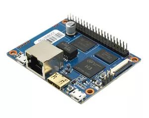
[[File:BPI-F2_zero_1.JPG|thumb|Overview BPI-F2 Zero with Allwinner H2+ chip]] | [[File:BPI-F2_zero_1.JPG|thumb|Overview BPI-F2 Zero with Allwinner H2+ chip]] | ||
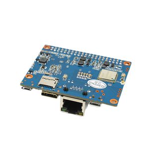
[[File:BPI-F2_zero_2.JPG|thumb|Overview BPI-F2 zero PoE support]] | [[File:BPI-F2_zero_2.JPG|thumb|Overview BPI-F2 zero PoE support]] | ||
| + | [[File:BPI-9600_POE_4.JPG|thumb|Banana Pi BPI-P2 Zero with BPI-9600 POE module]] | ||
Revision as of 23:52, 5 August 2018
Contents
[hide]Introduction
Banana Pi BPI-P2 Zero is an ultra compact single board computer measures only 65mm*52.5mm. It uses quad-core Cortex A7 allwinner H2+ processor(Option : H3 and H5), with 512MB RAM memory.8G eMMC flash,100M LAN,add PoE function support , It's ideal for light-weight systems with some space-limited applications. Like other members of Banana Pi, it supports both linux and android operating system.
Key Features
- CPU: Allwinner H2+, Quad-core Cortex-A7.
- 512MB DDR 3 SDRAM.
- WiFi (AP6212) & Bluetooth onboard.
- Mini HDMI.
- 40 PIN GPIO,It includes UART, SPI, I2C, IO etc
- 100M LAN
- IEEE 802.3af PoE standard PoE module support
- 8G eMMC flash onboard.
Getting Start
- Quick strart your BPI-M2 zero : Quick Start Banana pi SBC
- How to development : Getting Start with M2 Zero
Hardware
BPI-P2 Zero, just 3 change on BPI-M2 Zero . other hadware design same as BPI-M2 Zero.so all software is same .
- 1,add 8G eMMC flash support onboard, easy to do IoT gateway.
- 2,BPI-P2 Zero with 100M LAN interface ,BPI-M2 Zero with PIN define for 100M lan , use way is same.
- 3,PoE function support on board.
Hardware interfact
File:BPI-F2 zero interface.JPG
Hardware spec
| HardWare Specification of Banana pi BPI-P2 Zero VS BPI-M2 zero VS Raspberry Pi Zero W | |||
| Module | Banana Pi BPI-P2 Zero | Banana Pi BPI-M2 Zero | Raspberry Pi Zero W |
| CPU | H2+ Quad-core Cortex-A7 H265/HEVC 1080P | H2+ Quad-core Cortex-A7 H265/HEVC 1080P | Broadcom BCM2835 32 Bit 1 GHz ARM1176JZF-S single-core |
| GPU | Mali400MP2 GPU @600MHz,Supports OpenGL ES 2.0 | Mali400MP2 GPU @600MHz,Supports OpenGL ES 2.0 | VideoCore IV |
| Memory \(SDRAM\) | 512M DDR3(shared with GPU) | 512M DDR3(shared with GPU) | 512 MB DDR2 |
| Onboard Storage | TF card \(Max. 64GB\) | TF card \(Max. 64GB\) | TF card \(Max. 64GB\) |
| Onboard Network | 100M LAN | NOPE (but can extension with PIN define) | NOPE |
| PoE power | PoE function support | NOPE | NOPE |
| Onboard flash | 8G eMMC | NOPE | NOPE |
| Onboard WIFI | SDIO AP6212(option AP6181、AP6335) | SDIO AP6212(option AP6181、AP6335) | 802.11n wireless, Bluetooth 4.1 |
| Video decoding | 1080p@60fps,H.264 Video encoding 1080p@30fps,H.264 | 1080p@60fps,H.264 Video encoding 1080p@30fps,H.264 | 1080p30 H.264/MPEG-4 AVC high-profile decoder and encoder |
| Video input | A CSI input connector Camera | A CSI input connector Camera | CSI camera connector |
| Video Outputs | mini HDMI 1.4,1080P@30fps, DHCP | mini HDMI 1.4,1080P@30fps, DHCP | Mini HDMI and USB On-The-Go ports |
| Audio Output | Mini HDMI | Mini HDMI | Mini HDMI |
| Power Source | Micro USB with 5V/2A or PoE power | Micro USB with 5V/2A | 5V/2A |
| USB 2.0 Ports | one USB 2.0 OTG | one USB 2.0 OTG | one USB 2.0 OTG |
| Buttons | Power Button, Reset Button | Power Button, Reset Button | Composite video and reset headers |
| Low-level peripherals | 40 Pins Header,compatible with Raspberry Pi 3 | 40 Pins Header,compatible with Raspberry Pi 3 | 40 PIN |
| uart GPIO\(1x3\) pin | UART, ground | UART, ground | UART |
| LED | Power led & Status led | Power led & Status led | Power Status LED |
| IR | N/A | N/A | N/A |
| Supported OS | android linux | android linx | Linux |
| Product size | 65mm X 52.5mm | 65mm × 30mm | 65mm x 30mm |
| Weight | 30g | 15g | 9g |
GPIO PIN define
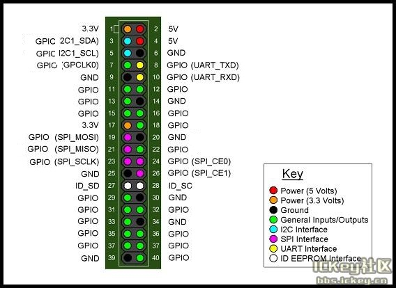
Banana Pi BPI-P2 zero GPIO same as BPI-M2 Zero ,it has a 40-pin GPIO header that matches that of the Model Raspberry Pi 3. Following is the Banana Pi GPIO Pinout:
| 40 PIN GPIO of Banana pi BPI-P2 Zero | |||
| GPIO Pin Name | Default Function | Function2:GPIO | Function3 |
| CON2-P01 | VCC-3V3 | ||
| CON2-P02 | VCC-5V | ||
| CON2-P03 | TWI0-SDA | PA12-EINT12 | |
| CON2-P04 | VCC-5V | ||
| CON2-P05 | TWI0-SCK | PA11-EINT11 | |
| CON2-P06 | GND | ||
| CON2-P07 | PWM1 | PA6-EINT6 | |
| CON2-P08 | UART3-TX | PA13-EINT13 | SPI1-CS |
| CON2-P09 | GND | ||
| CON2-P10 | UART3-RX | PA14-EINT14 | SPI1-CLK |
| CON2-P11 | UART2-RX | PA1-EINT1 | |
| CON2-P12 | UART3-CTS | PA16-EINT16 | SPI1-MISO |
| CON2-P13 | UART2-TX | PA0-EINT0 | |
| CON2-P14 | GND | ||
| CON2-P15 | UART2-CTS | PA3-EINT3 | |
| CON2-P16 | UART3-RTS | PA15-EINT15 | SPI1-MOSI |
| CON2-P17 | VCC-3V3 | ||
| CON2-P18 | PC4 | PC4 | |
| CON2-P19 | SPI0-MOSI | PC0 | |
| CON2-P20 | GND | ||
| CON2-P21 | SPI0-MISO | PC1 | |
| CON2-P22 | UART2-RTS | PA2-EINT2 | |
| CON2-P23 | SPI0-CLK | PC2 | |
| CON2-P24 | SPI0-CS | PC3 | |
| CON2-P25 | GND | ||
| CON2-P26 | PC7 | PC7 | |
| CON2-P27 | TWI1-SDA | PA19-EINT19 | |
| CON2-P28 | TWI1-SCK | PA18-EINT18 | |
| CON2-P29 | PA7-EINT7 | PA7-EINT7 | |
| CON2-P30 | GND | ||
| CON2-P31 | PA8-EINT8 | PA8-EINT8 | |
| CON2-P32 | PL2-S-EINT2 | PL2-S-EINT2 | |
| CON2-P33 | PA9-EINT9 | PA9-EINT9 | |
| CON2-P34 | GND | ||
| CON2-P35 | PA10-EINT10 | PA10-EINT10 | |
| CON2-P36 | PL4-S-EINT4 | PL4-S-EINT4 | |
| CON2-P37 | PA17-EINT17 | PA17-EINT17 | SPDIF-OUT |
| CON2-P38 | PA21-EINT21 | PA21-EINT21 | |
| CON2-P39 | GND | ||
| CON2-P40 | PA20-EINT20 | PA20-EINT20 | |
CSI Camera Connector specification:
The CSI Camera Connector is a 24-pin FPC connector which can connect external camera module with proper signal pin mappings. The pin definitions of the CSI interface are shown as below. This is marked on the Banana Pi board as “CSI″.
| 24 PIN CSI Camera connector of Banana pi BPI-P2 Zero | |||
| CSI Pin Name | Default Function | Function2:GPIO | |
| CN3-P01 | NC | ||
| CN3-P02 | GND | ||
| CN3-P03 | CSI0-SDA | PE13 | |
| CN3-P04 | CSI0-AVDD | ||
| CN3-P05 | CSI0-SCK | PE12 | |
| CN3-P06 | CSI0-Reset | PE14 | |
| CN3-P07 | CSI0-VSYNC | PE3 | |
| CN3-P08 | CSI0-PWDN | PE15 | |
| CN3-P09 | CSI0-HSYNC | PE2 | |
| CN3-P10 | CSI0-DVDD | ||
| CN3-P11 | CSI0-DOVDD | ||
| CN3-P12 | CSI0-D7 | PE11 | |
| CN3-P13 | CSI0-MCLK | PE1 | |
| CN3-P14 | CSI0-D6 | PE10 | |
| CN3-P15 | GND | ||
| CN3-P16 | CSI0-D5 | PE9 | |
| CN3-P17 | CSI0-PCLK | PE0 | |
| CN3-P18 | CSI0-D4 | PE8 | |
| CN3-P19 | CSI0-D0 | PE4 | |
| CN3-P20 | CSI0-D3 | PE7 | |
| CN3-P21 | CSI0-D1 | PE5 | |
| CN3-P22 | CSI0-D2 | PE6 | |
| CN3-P23 | GND | ||
| CN3-P24 | CSI0-DOVDD | ||
UART specification:
The jumper CON3 is the UART interface. For developers of Banana Pi, this is an easy way to get the UART console output to check the system status and log message.
| jumper CON3 of Banana pi BPI-P2 Zero | |||
| CON3 Pin Name | Default Function | GPIO | |
| CON3 P03 | UART0-TXD | PA4 | |
| CON3 P02 | UART0-RXD | PA5 | |
| CON3 P01 | GND | ||
PoE support
we deign a IEEE 802.3af PoE module for BPI-P2 Zero ,easy to support PoE function,more spec ,please check BPI-9600 PoE module spec
Resources
Documents
- Allwinner documents:
- allwinner H3 chip doc baidu link: https://pan.baidu.com/s/1qTULll2CR02d0Hw9itq1rw
- Allwinner H2+ chip doc baidu link: https://pan.baidu.com/s/1TGMYr3rhizfhlg5hl6hLyg
Source code
- Android 4.4 source code
- Linux source code
- kernel 3.4 source code : https://github.com/BPI-SINOVOIP/BPI-M2Z-bsp


