Difference between revisions of "BPI-Bit-S2"
(→Hardware interface) |
(→Hardware upgrade and function comparison) |
||
| Line 61: | Line 61: | ||
| WIFI | | WIFI | ||
|- | |- | ||
| − | | | + | | LED |
| − | | 25 WS2812-5050 | + | | 25 WS2812-5050 RGB LED |
| − | | 25 WS2812-3535 | + | | 25 WS2812-3535 RGB LED |
|- | |- | ||
| Key | | Key | ||
| Line 69: | Line 69: | ||
| 2 programmable keys,1 BOOT key,1 RST key | | 2 programmable keys,1 BOOT key,1 RST key | ||
|- | |- | ||
| − | | | + | | Buzzer |
| 5.3x5.3mm buzzer | | 5.3x5.3mm buzzer | ||
| 8.5x8.5mm buzzer | | 8.5x8.5mm buzzer | ||
| Line 81: | Line 81: | ||
| None | | None | ||
|- | |- | ||
| − | | | + | | Battery socket |
| support | | support | ||
| None | | None | ||
| Line 93: | Line 93: | ||
| None | | None | ||
|- | |- | ||
| − | | | + | | Photosensitive sensor |
| 2 | | 2 | ||
| 2 | | 2 | ||
|- | |- | ||
| − | | | + | | Thermistor sensor |
| 1 | | 1 | ||
| 1 | | 1 | ||
Revision as of 19:07, 5 December 2022
Contents
About BPI-Bit-S2
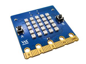
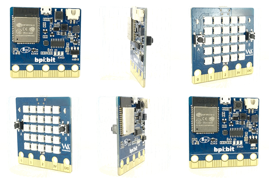
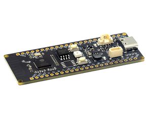
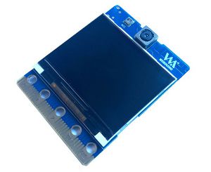
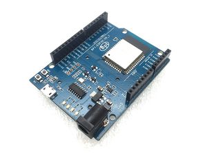
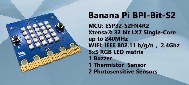
BPI-Bit-S2 development board is a successor to BPI:Bit, inheriting most of the core hardware functions.
Support Webduino, Arduino, MicroPython programming environment suitable for STEAM education.
key features
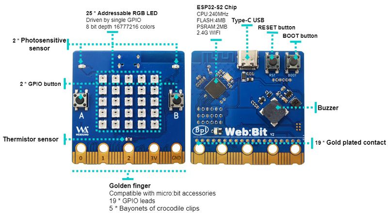
- ESP32-S2
- 5x5 RGB LED matrix
- 1 buzzer
- 1 thermistor sensor
- 2 photosensitive sensors
- 2 buttons on the front, 1 reset button and 1 boot button on the back
- Type-C USB interface
- Size 5x5cm
- The Goldfinger Edge Connector definition is fully compatible with Micro: Bit
Hardware upgrade and function comparison
| BPI:Bit VS BPI-Bit-S2 | ||
|---|---|---|
| Module | BPI:Bit | BPI-Bit-S2 |
| SoC control chip | ESP32 | ESP32-S2 |
| ROM | 448 KB | 128 KB |
| RAM | 520 KB | 320 KB |
| FlASH ROM | 4096 KB | 4096 KB |
| PSRAM | None | 2048 KB |
| Wireless Capability | WIFI,Bluetooth | WIFI |
| LED | 25 WS2812-5050 RGB LED | 25 WS2812-3535 RGB LED |
| Key | 2 programmable keys,1 RST key | 2 programmable keys,1 BOOT key,1 RST key |
| Buzzer | 5.3x5.3mm buzzer | 8.5x8.5mm buzzer |
| USB interface | Micro USB | Type-C USB |
| USB to TTL | support | None |
| Battery socket | support | None |
| IO | 19 pin Goldfinger IO | 19 pin Goldfinger IO |
| Nine-axis sensor | support | None |
| Photosensitive sensor | 2 | 2 |
| Thermistor sensor | 1 | 1 |
Hardware interface
| BPI-Bit-S2 specification | |
|---|---|
| SoC | ESP32-S2FN4R2,Xtensa® 32 bit LX7 Single-Core Processer |
| frequency | 240MHz MAX |
| operating temperature | -40℃~+85℃ |
| ROM | 128 KB |
| SRAM | 320 KB |
| FLASH ROM | 4 MB |
| PSRAM | 2 MB |
| WIFI | IEEE 802.11 b/g/n ,2.4Ghz |
| GPIO | 19 available GPIO pins have been introduced |
| Peripheral functions | ADC,TOUCH,PWM,SPI,I2C,I2S,Pulse counter, RMT,TWAI® Controller,SD/MMC,LCD_CAMERA |
| external crystal | 40Mhz |
| Buzzer | 8.5x8.5mm buzzer |
| LED | 25 Series full color LED lamp, single line GPIO control; 1 monochrome LED, CONTROLLED by GPIO |
| photosensitive sensor | 2 photosensitive sensor |
| thermistor sensor | 1 thermistor sensor |
| IO | 19 pins Goldfinger IO,19 pins contacts on the back |
| Key | 2 Programmable buttons,1 BOOT botton,1 reset botton |
| USB | USB Type-C interface,full speed USB OTG,USB-ACM |
| operating voltage | 3.3V |
| Power | USB Type-C input 5V,or Goldfinger IO input 3.3V power supply |
| size | 5 * 5 cm |
On-board peripherals
| Peripheral GPIO allocation and signal type | ||
|---|---|---|
| photosensitive sensor(L) | GPIO 12 | Analog Input |
| photosensitive sensor(R) | GPIO 13 | Analog Input |
| Key A | GPIO 38 | Digital Input |
| Key B | GPIO 33 | Digital Input |
| Key BOOT | GPIO 0 | Digital Input |
| thermistor sensor | GPIO 14 | Analog Input |
| buzzer | GPIO 17 | PWM(Digital Output) |
| RGB_LED | GPIO 18 | Digital Output |
5*5 Full color LED lights
BPI-Bit-S2 have 25 Full color LED lights , single GPIO ontrol.The three primary color pixels of each LED can achieve 8bit 256 level brightness display, and achieve 16777216 color full color display, scanning frequency is not less than 400Hz/s.
| 5*5 LEDs list of BPI-Bit-S2 | ||||
|---|---|---|---|---|
| 20 | 15 | 10 | 5 | 0 |
| 21 | 16 | 11 | 6 | 1 |
| 22 | 17 | 12 | 7 | 2 |
| 23 | 18 | 13 | 8 | 3 |
| 24 | 19 | 14 | 9 | 4 |
Goldfinger GPIO define
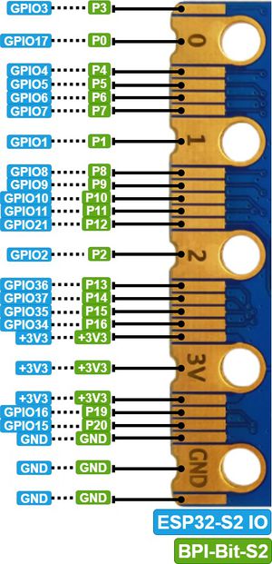
BPI-Bit-S2 Gold finger GPIO is defined to be compatible with Micro:Bit. GPIO expansion board accessories can be used with Micro: Bit.
| SPI,I2C | ||
|---|---|---|
| Function | Pin Name | GPIO Num |
| SPI_SCK | P13 | GPIO36 |
| SPI_MISO | P14 | GPIO37 |
| SPI_MOSI | P15 | GPIO35 |
| SPI_CS | P16 | GPIO34 |
| I2C_SCL | P19 | GPIO16 |
| I2C_SDA | P20 | GPIO15 |
Power
BPI-Bit-S2 supports two power supply modes
1. Type-C USB:Use USB cable power supply, connect USB interface of computer or other 5V USB charger to power the development board.
2. Gold finger: At the bottom of the development board, the gold finger contains a power interface with both input and output functions. It uses 3.3V power supply, positive terminal is connected to 3V3, and negative terminal is connected to GND.
Software
Webduino
Arduino
Arduino 是一个开源嵌入式软硬件开发平台,用来供用户制作可交互式的嵌入式项目。
Preparing...
MicroPython
MicroPython实现了大部分Python 3 特性和语法,易学易上手,验证程序效果无需编译直接下载进芯片运行。
无论是否有编程基础,MicroPython的上手难度绝对远低于其他编程语言,其代码易读性高,且开源社区有多年积累的丰富资源,就如同Python一样拥有极强的生命力与应用价值。
Preparing...
