Difference between revisions of "Getting Started with Triode-Car"
(→Use Two Micro: bit to Control Eachother's Motors Through Radio) |
|||
| Line 135: | Line 135: | ||
#Releasing all buttons to stop. | #Releasing all buttons to stop. | ||
| − | + | The four variables added are not superfluous. Although you can also fill in the values we need in the building blocks, using variable names to replace these specified values helps us to establish a clearer cognitive logic. The more complex procedures can reflect its value. | |
'''Example link:'''https://github.com/Wind-stormger/Makecode/blob/master/microbit-Triode-Car_radio_control_1.hex | '''Example link:'''https://github.com/Wind-stormger/Makecode/blob/master/microbit-Triode-Car_radio_control_1.hex | ||
Revision as of 18:33, 20 July 2021
Contents
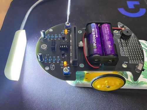
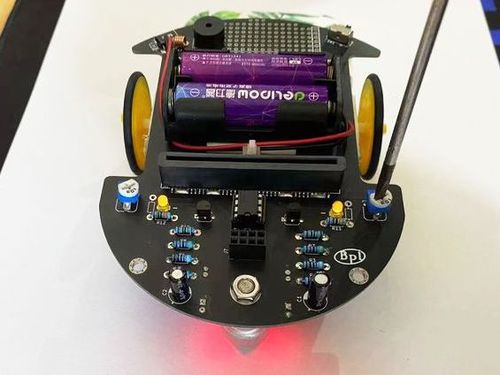
Product Introduction
Control With LM393 Chip
Hardware Introduction
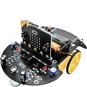
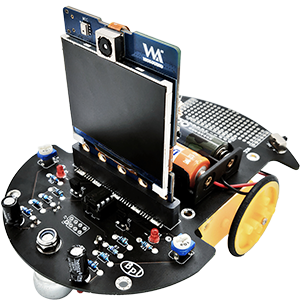
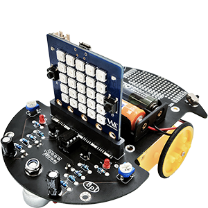
There is a button to switch between two modes on the Triode-Car. One of which is using the built-in LM393 comparator chip, and the other is with the Micro: bit or BPI: bit.
When using the built-in LM393 chip, it has only one function, to track dark lines, it consists of the Line Detecting Circuit, Voltage Comparing Circuit, and the Motor Circuit.
Line Detecting Circuit
The Triode-Car uses two pairs of photoresistor and LED on the bottom side to enable its line tracking feature. When the LED light reflecs on bright and dark surfaces, the resistance of the photoresistor will change drastically.
The photoresistor used on Triode-Car is the GL5506, this photoresistor can have a resistance as high as 0.2MΩ in the dark(10Lux), while in the light(400~600Lux), it can have a resistance as low as a 2-5KΩ.
(Bright resistance: Tested after shining with 400~600Lux light for 2 hours, then shine it with a standard 10Lux, with a color temperature of 2854K light source.) (Dark resistance: Tested on the 10th second after shutting off the 10Lux light source.)
Voltage Comparing Circuit
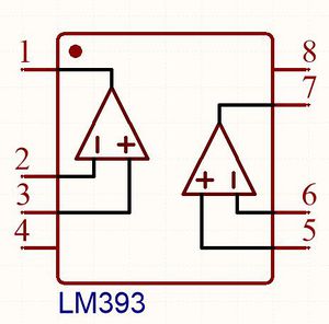
The Voltage Comparing Circuit includes the LM393 chip and several resistors. The LM393 consists of two independent precision voltage comparators with a low offset voltage. Its use is to compare two input voltages, then changes the output voltage accordingly. When the positive voltage from the comparator is higher than reverse voltage, the output will output high signal. When the positive voltage is lower than reverse voltage, it will output low signal. The LM393's output is open collector type, so a pull high resistor is needed here.
Motor Circuit
The S8550 PNP triode plays an important role in the motor circuit. It uses a small base current and a negative base voltage to control a larger emitter-collector current. With a maximum collector current of 1.5A, it can be used as a low level switch.
Control Circuit
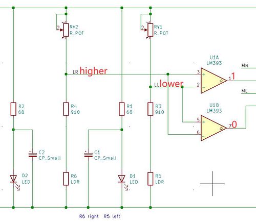
As the picture shown above, when the car shifts towards the left, the right photoresistor will be directly on top of the line, therefore, its resistance will increase. Conversely, the left resistor, will shift away from the line, its resistance will decrease. At this point, the voltage from LL will be lower than LR. The U1A comparator's positive voltage will be higher than reverse voltage, triggering pin 1 to pull high. Conversely, U1B's positive voltage will be lower than reverse voltage, pin 7 will pull low, making the left motor move. The car shifts right, R6 and D2 moves away from the dark line until the left sensors detect the dark line. The concept is similar as before, the car repeats the actions above to progress forward.
Calibrating Line-Detecting Sensitivity
To calibrate the Line-Detecting sensitivity under LM393 control, one would need to adjust the potentiometers physically. This process could help the Triode-Car to detect dark lines more.
Calibration process are as follows:
- Point a stable light source towards the photoresistors.
- Adjust either side of potentiometers until both motors are operating simultaneously.
- After adjustments, put the car on the track to test the results.
- If the car still runs off course, place the car on a white piece of paper, use a small object to lift up the back wheels slightly to prevent contact, repeat the steps 2~3 to adjust the potentiometers.
Use MakeCode to Control the Triode-Car
This is a tutorial on how to control the Triode-Car with Micro:bit Makecode.
Beginner Tutorial
Adding the Triode-Car Extention to Control with Micro: bit
It is recommended for beginners to install the extension blocks by typing in the extensions search bar: " https://github.com/bpi-steam/pxt-triodecar" to add extentions. Click to import the Triode-Car extension pack.
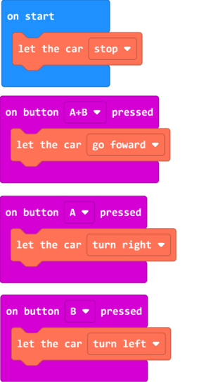
- As the blocks shown, the car will stop after bootup or reset.
- Pressing down button A and B at the same time will make the car go forward.
- Press A to turn Right.
- Press B to turn Left.
Example link:https://github.com/Wind-stormger/Makecode/blob/master/microbit-Triode-car_motor_control_1.hex
Project files can be downloaded and edit locally by importing to MakeCode, or flash it directly onto the Micro:bit via USB to run it directly.
Motor Speed Adjustment
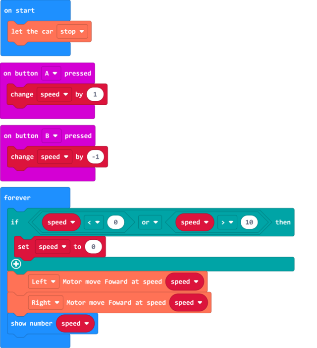
In the Triode-Car extensions, there are blocks dedicated to adjust the speed up to 10 levels.
Example Blocks:
- When button A is pressed, the speed increases by 1 level
- Press button B once, the speed decreases by 1 level
- Micro: bit display current speed.
The code within "forever" block will loop forever after the code in "on start" finishes. In between each loop, it can perform other actions such as, on button A/B pressed.
加入了一个"if"判断积木,若变量"speed"值小于0或大于10时,将变量"speed"值设为0,这样可以将值限定在0到10范围内不会溢出而报错。
Example link: https://github.com/Wind-stormger/Makecode/blob/master/microbit-Triode-car_motor_control_2.hex
Project files can be downloaded and edit locally by importing to MakeCode, or flash it directly onto the Micro:bit via USB to run it directly.
Reading Analog Signals From Photoresistors
For Hardware Design, please refer to (Line Detecting Circuit).
The "Read (index) line tracking sensor" block in Triode-Car extensions can collect analog values from the photoresistors.
Micro: bit pins' voltage can be set from 0~3.3v, and has 1024(10bit) precision levels, therefore, the "read left/right line tracking sensor" block will input an analog value to adjust its voltage ranging from 0~1023.
Example Blocks:
In the program, every 100ms the two photoresistors will send its analog values through USB port to the computer. By opening the control panel in Makecode, we can see the exact values.
Example link: https://github.com/Wind-stormger/Makecode/blob/master/microbit-Triode-car_read_LDR.hex
Project files can be downloaded and edit locally by importing to MakeCode, or flash it directly onto the Micro:bit via USB to run it directly.
Use Two Micro: bit to Control Eachother's Motors Through Radio
Micro: bit supports radio connection, enable the radio extension on micro: bit, then it is possible for two micro: bit to communicate with eachother.
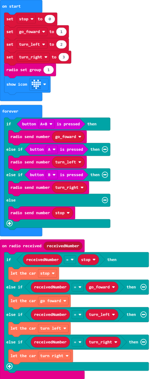
Example Blocks:
By flashing the program onto the Micro: bit, and installing onto the Triode-Car, we can control the other car by pressing A/B buttons.
- Pressing button A allows it to turn left
- Pressing button B to turn right
- Pressing button A+B to go forward
- Releasing all buttons to stop.
The four variables added are not superfluous. Although you can also fill in the values we need in the building blocks, using variable names to replace these specified values helps us to establish a clearer cognitive logic. The more complex procedures can reflect its value.
Example link:https://github.com/Wind-stormger/Makecode/blob/master/microbit-Triode-Car_radio_control_1.hex
Project files can be downloaded and edit locally by importing to MakeCode, or flash it directly onto the Micro:bit via USB to run it directly.
Bluetooth Control
The bluetooth feature can be enabled through MakeCode extensions, we can control the micro: bit with our smartphones through certain applications.
- iOS users: Micro:bit App on App Store
- Android users:Microbit-blue GitHub linkor: Kitronik Move on Google Play Store
Note: There is an official release of the Micro: bit App on both the iOS App Store and Android's Google Play Store, however, the iOS version has support for bluetooth connection, whereas the Google Play store's does not. This is why we require third party apps on Android devices that supports bluetooth connection.
Bluetooth pairing process and notes:
- In the MakeCode editor, open the extensions on the bottom of advanced tab, click on the bluetooth extension icon to apply.Bluetooth and Radio extensions cannot coexist, choosing bluetooth will automatically remove radio extension.
- When pairing the micro: bit with android third-party app, one could turn on "Passkey pairing: Paring requires 6 digit key to pair." option in Project settings.
- To enter pairing mode, connect micro: bit to power, press reset button once while holding A+B button.
Do NOT let go of A+B buttons while the progress bar is running, it would interrupt the pairing process and one would need to start over.
- Android devices need to turn on GPS and bluetooth to have a stable connection.
- On Android devices, navigate to bluetooth settings, find and pair with the micro: bit. Once the pairing process starts, micro: bit will hint to press button A once, then it would scroll a 6 digit pairing code. Enter the code on the Andriod device to complete the pairing process.
- Press the reset button on the Micro: bit after pairing to restart.
- iOS devices does not require to enter bluetooth settings. To pair with the micro: bit, please follow the pairing instructions in the official micro: bit app.
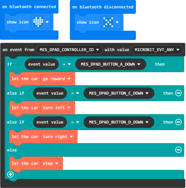
Example Blocks:
When paired successfully with bluetooth, display a red heart, whereas a disconnection would display an "X" symbol. Press the buttons inside the app to control the Triode-Car wirelessly. Press button A to go forward, C to turn left, and D to turn right, release the buttons to stop.
The "on event from()with value()" block can be found in the Control tab in Makecode.
Example link:https://github.com/Wind-stormger/Makecode/blob/master/microbit-Triode-car_bluetooth_control_1.hex
Project files can be downloaded and edit locally by importing to MakeCode, or flash it directly onto the Micro:bit via USB to run it directly.
Advanced Tutorial
Calibrating the Line-Detecting Circuit
As every component are not made exactly the same, despite being made according to the datasheet, they would vary from eachother ever so slightly. Calibration of the Line-Following Circuit improves the reaction time of the Triode-Car's line tracking feature. Adjust the resistance of the potentiometers connected to the photoresistors to increase the sensitivity. This process makes the Triode-Car less likely to run off course and maintains a stable analog voltage output.
We can directly use the "Reading Analog Signals From Photoresistors" guide from beginners tutorial to read the analog signals from the computer, then manually adjust the potentiometer with a screwdriver.
The Micro: bit can detect analog voltage values from 0~1023, the closer the value is to the middle, the reaction from changes of brightness detected by the photoresistor will become more sensitive.
Therefore, under a stable brightness environment, try to calibrate the resistance as close to 512 as possible. This would create more stable energy output and reduce their analog value difference.
The above steps mentioned requires constant connection with triode-car connected to micro: bit and then to the PC. In a real use case scenerio, one would best be using manual adjustments to increase the sensitivity.
We cannot be sure to have the micro: bit connected to the PC all the time, therefore, we need to write a program to guide us how to properly calibrate the sensitivity.
Calibration Steps:
- Adjust the left potentiometers first, to make its analog value out close to the median.
- 在上一个条件满足的前提下调整右侧的可调电阻,使其并联的光敏电阻在Micro:Bit对应引脚上输出的电压模拟量接近另一个光敏电阻。
We can achieve this by creating a simple "if" statement program. For those people who adjust manually, we could add different image patterns to indicate if we have adjusted properly.
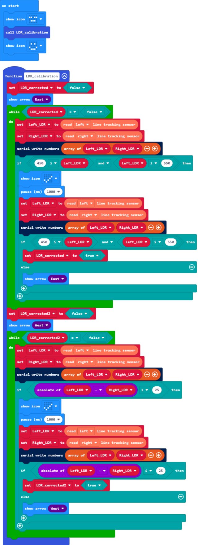
Example Blocks:
The code is a bit complex, detailed explaination are as follows:
- 将程序整体放入一个"function"自定义函数中,这有利于我们从认知上在大量积木中区分某一部分的功能,方便后续调用或维护。
- 整体由两个"while"循环积木组成,加入了循环条件,这样可以在可调电阻校准完成后改变循环条件退出循环。
- 在进入"while"循环之前,使Micro:Bit显示对应的方向指示,给人以直观的行动目标,确认当前应该要进行手动调整的可调电阻。
- 第一个"while"循环积木中的程序用于校准左侧光敏电阻,其中"if"判断条件为,左侧光敏电阻输出的电压模拟量大于等于450小于等于550。
- 当满足第4条中的"if"判断条件后,使Micro:Bit显示一个表示正确的图形,给人以视觉上反馈,此时人应该停止对左侧的可调电阻的调节,随后延时1000ms再一次进行相同的"if"判断条件,用以消除手动调整可能产生的抖动而带来的误差,当再次确认条件满足时,改变控制这个"while"循环的循环条件以退出循环,执行下一步。
- 第二个"while"循环积木中的程序用于校准右侧光敏电阻,其中"if"判断条件为,左右两侧光敏电阻输出的电压模拟量相减,其差值的绝对值小于等于25。
例程项目文件:https://github.com/Wind-stormger/Makecode/blob/master/microbit-Triode-car_LDR_calibration_2.hex
项目文件下载到本地后可导入MakeCode中查看和再编辑,也可直接通过USB烧录到Micro:Bit中直接运行。
巡线行驶
在“校准巡线检测电路”之后,我们即可开始对巡线检测电路进行有效利用。
根据“巡线检测电路”中所介绍的原理,巡线需要利用“线路”与其两侧路面对光线不同的反射率进行实时的光照强度检测,在程序中读取左右两个光敏电阻的电压模拟值,对数值进行比对,以此判断Triode-Car行进路线是否发生偏移以及偏移方向,进而对左右两个电机的启停进行控制,修正Triode-Car的行驶方向,达成沿着“线路”行驶的目的。
例程如下图所示。
由于例程较为复杂,所以给出一些必要的说明:
- "on button A pressed"积木用于控制循迹程序的启动和停止,每按一次按钮A,其中设置的变量就会改变一次状态。
- "forever"积木将重复执行其内部的程序,每次循环结束或在循环中执行到"show"或"pause"积木时会让出线程允许其他的"forever"积木或事件处理程序运行,所以此处三个"forever"积木与一个"on button A pressed"积木可以共同在后台运行,这样使系统具备同时执行多个程序的能力,一般将此称作“多工”。
- 第一个"forever"积木内的程序用于循环读取左右两个光敏电阻电压模拟值,然后在多级"if"条件积木中进行判断,满足相应条件时改变变量,该变量用于控制电机。
- 第二个"forever"积木内的多级"if"条件积木对第一个"forever"积木内改变的变量值进行判断,直接输出控制信号来控制左右电机的启停和转速。
- 第一,二个"forever"积木内的循环条件即为"on button A pressed"积木控制的变量,变量为"true"值时才会循环执行。
- 第三个"forever"积木略有巧思,其内部的循环仅在用于控制电机的变量发生变化时才会执行一次,对应改变LED当前应当显示的内容。
例程项目文件:https://github.com/Wind-stormger/Makecode/blob/master/microbit-Triode-car_Line_Follower.hex
项目文件下载到本地后可导入MakeCode中查看和再编辑,也可直接通过USB烧录到Micro:Bit中直接运行。
