|
|
| (24 intermediate revisions by the same user not shown) |
| Line 1: |
Line 1: |
| | =Introduction= | | =Introduction= |
| | | | |
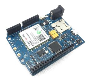
| − | [[File:BPI_NB-IoT_linaro_1.JPG|thumb|Overview]] | + | [[File:BPI_NB-IoT_arduino_1.JPG|thumb|Overview]] |
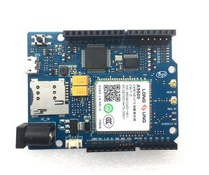
| − | [[File:BPI_NB-IoT_linaro_2.JPG|thumb|Overview]] | + | [[File:BPI_NB-IoT_arduino_5.JPG|thumb|Overview:front]] |
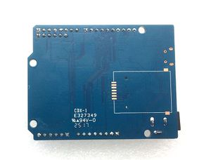
| | + | [[File:BPI_NB-IoT_arduino_6.JPG|thumb|Overview:back]] |
| | | | |
| − | BPI-GSM is a development board based on ATmega2560 MCU,using 16 MHz crystal oscillator. It features 54 digital I/O (14 of which can be used as PWM),16 analog input, 4 UART (hardware serial ports). Connected with SIM808 GSM module through serial port, it can make phone call,text,GPS positioning.Equipped with high precision DHT22 temperature and humidity sensor,data can be displayed on BPI LED.The board is powered by 2500MA lithium battery and can be charged with USB. A simple application of BPI-GSM is mobile environment monitors.
| |
| | | | |
| − | The peripheral modules of Arduino are growing fast due to the open source as well as the developing environment which uses C language borrowed java cross platform concept. And the main reason that attracts Artist to use Arduino is the easy and fast communication with other software such as Flash and Processing using Arduino language to create interactive multimedia works. The IDE of Arduino is open source, which enables you free download to create your own works such as special topic,school teaching,motor control...
| + | BPI NB-IoT Arduino development board with Qualcomm chip design |
| | | | |
| − | BPI-GSM has two power options, USB or external, and it can switch automatically.For external power option,you can choose AC-to-DC adapter(5V,2A) or battery, and the voltage range should be 4.5V - 5.5V, it might be unstable if voltage drops under 4.5V due to the 5V level can not be guaranteed on I/O pins. If the voltage exceeds 5.5V, power regulator may trigger thermal protection, more harm would be to BPI-GSM if over-voltage continues. So the recommended operational power is 4.5V-5.5V, 2A rating.
| |
| | == Key Features == | | == Key Features == |
| | | | |
| − | * photocell: measuring the current light luminance;
| + | =Hardware= |
| − | * high precision temperature&humidity sensor: measure current temperature and relative humidity
| + | |
| − | * GSM module: can be used to make phone call, text,2G connectivity,GPS positioning.
| + | == Hardware Spec== |
| − | * Developed on Arduino, with the main chip:2560,communicate with Arduino using AT command
| |
| − | * support powered by battery.
| |
| | | | |
| − | =Hardware=
| |
| | | | |
| − | {| class="wikitable"
| |
| − | |-
| |
| − | | style="background: PaleTurquoise; color: black" colspan="4"| ''HardwareSpecification of BPi GSM moudle''
| |
| − | |-
| |
| − | |Microcontroller||ATmega2560
| |
| − | |-
| |
| − | |Operating Voltage|| 5V
| |
| − | |-
| |
| − | |Digital I/O Pins|| 54 (of which 15 provide PWM output)
| |
| − | |-
| |
| − | |Analog Input Pins|| 16
| |
| − | |-
| |
| − | |DC Current per I/O Pin ||40 mA
| |
| − | |-
| |
| − | |DC Current for 3.3V Pin|| 50 mA
| |
| − | |-
| |
| − | |Flash Memory|| 256 KB of which 8 KB used by bootloader
| |
| − | |-
| |
| − | |SRAM|| 8 KB
| |
| − | |-
| |
| − | |EEPROM ||4 KB
| |
| − | |-
| |
| − | |Clock Speed||16MHz
| |
| − | |-
| |
| − | |}
| |
| | | | |
| | ==BPI-GSM sketch map == | | ==BPI-GSM sketch map == |
| − | [[File:BPI-GSM_sketch_map.JPG]]
| |
| | | | |
| − | =Software=
| |
| | | | |
| − | ==How to use BPI-GSM module==
| |
| − | test code download:https://drive.google.com/file/d/0B4PAo2nW2KfnOWxXeTdkWlY0c2c/view?usp=sharing
| |
| | | | |
| − | Please use arduino 1.6.6 Ver IDE,if you know arduino,it is easy to use.
| + | == GPIO Pin define == |
| | | | |
| − | [[File:Use_1.JPG]]
| |
| | | | |
| − | [[File:Use_2.JPG]]
| |
| | | | |
| − | [[File:Use_3.JPG]]
| + | =Software= |
| | | | |
| − | [[File:Use_4.JPG]]
| |
| | | | |
| − | [[File:Use_5.JPG]]
| |
| | | | |
| | =Resources= | | =Resources= |
| − | BPI-GSM module schematic diagram : https://drive.google.com/file/d/0B4PAo2nW2Kfnekg2S0JLaHVxbkU/view?usp=sharing
| |
| − |
| |
| − | Video demo on youtube: https://www.youtube.com/watch?v=ezc8UDYJUBM&feature=youtu.be
| |


