Difference between revisions of "BPI-NANO arduino NANO board"
(→Hardware spec) |
|||
| (31 intermediate revisions by the same user not shown) | |||
| Line 1: | Line 1: | ||
| + | [[zh:BPI-NANO Arduino开源开发板]] | ||
| + | |||
| + | |||
=Overview= | =Overview= | ||
| + | |||
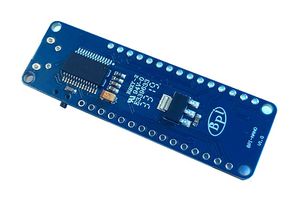
| + | [[File:BPI-Nano_1.JPG|thumb|BPI-Nano arduino Nano]] | ||
| + | [[File:BPI-Nano_2.JPG|thumb|BPI-Nano arduino Nano]] | ||
| + | [[File:Leaf-S3-incline-front.jpg|thumb|[[BPI-Leaf-S3]] with ESP32-S3]] | ||
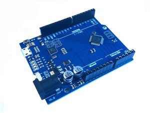
| + | [[File:BPI-UNO_1.JPG|thumb|[[BPI-UNO arduino UNO board]]]] | ||
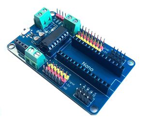
| + | [[File:BPI-Nano_robort_2.JPG|thumb|[[BPI-Nano robot board]]]] | ||
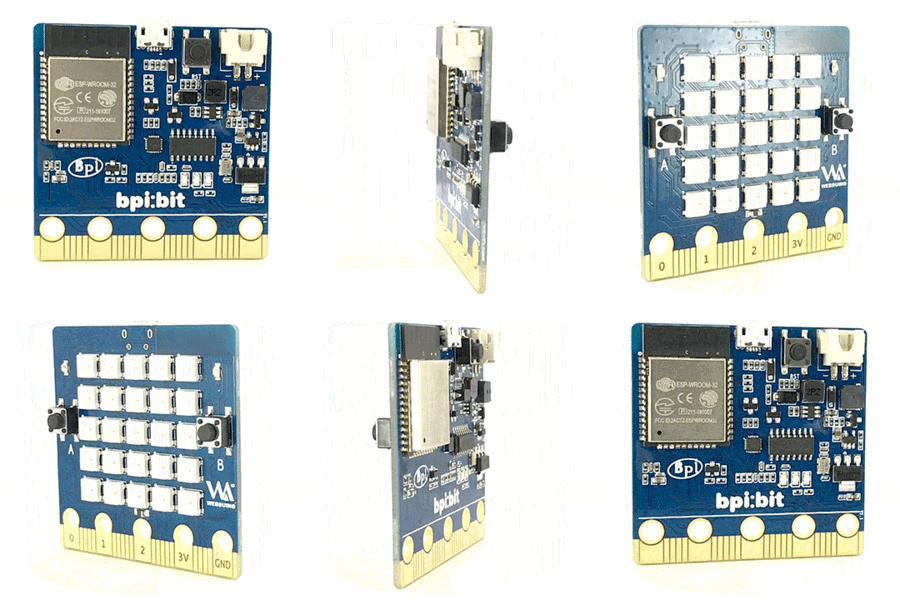
| + | [[File:Webduino_gif.gif|thumb|Overview: BPI:bit]] | ||
| + | [[File:BPI-AI_1.JPG|thumb|[[BPI-AI]] Kendryte K210 RISC-V]] | ||
| + | [[File:Q-Car_With_Web_Bit.png|thumb|[[BPI Q-Car kit]] with BPI:Bit board]] | ||
| + | [[File:BPI-bit_robort_board_3.JPG|thumb|[[BPI:bit robot expansion board]]]] | ||
| + | |||
| + | |||
The BPI-Nano is a Arduino Nano board, it is a small, complete, and breadboard-friendly board based on the ATmega328 (same Arduino Nano 3.0), It has more or less the same functionality of the Arduino Duemilanove. It lacks only a DC power jack, and works with a Mini-B USB cable instead of a standard one. The Nano was designed and is being produced by Gravitech.made by sinovoip | The BPI-Nano is a Arduino Nano board, it is a small, complete, and breadboard-friendly board based on the ATmega328 (same Arduino Nano 3.0), It has more or less the same functionality of the Arduino Duemilanove. It lacks only a DC power jack, and works with a Mini-B USB cable instead of a standard one. The Nano was designed and is being produced by Gravitech.made by sinovoip | ||
| Line 16: | Line 31: | ||
{| class="wikitable" | {| class="wikitable" | ||
|- | |- | ||
| − | | style="background: PaleTurquoise; color: black" colspan="4"| '''Banana Pi BP- | + | | style="background: PaleTurquoise; color: black" colspan="4"| '''Banana Pi BP-Nano''' |
|- | |- | ||
|Microcontroller || ATmega328P | |Microcontroller || ATmega328P | ||
| Line 26: | Line 41: | ||
|Input Voltage: (limits) ||6-20V | |Input Voltage: (limits) ||6-20V | ||
|- | |- | ||
| − | |Digital I/O Pins ||14( | + | |Digital I/O Pins ||14(include 6 PWM output) |
|- | |- | ||
|PWM PIN ||6个 | |PWM PIN ||6个 | ||
| Line 36: | Line 51: | ||
|3.3V output Max|| 50mA | |3.3V output Max|| 50mA | ||
|- | |- | ||
| − | |Flash|| 32KB(ATmega328P) | + | |Flash|| 32KB(ATmega328P) and 0.5KB used by bootloader |
|- | |- | ||
|SRAM|| 2KB(ATmega328P) | |SRAM|| 2KB(ATmega328P) | ||
| Line 52: | Line 67: | ||
There is a self-restoring fuse on the bpi-uno that automatically disconnects the power supply when short-circuiting or overcurrent exceeds 500mA, thus protecting the USB port and bpi-uno of the computer. While most computer USB ports provide internal protection, this fuse provides additional protection. | There is a self-restoring fuse on the bpi-uno that automatically disconnects the power supply when short-circuiting or overcurrent exceeds 500mA, thus protecting the USB port and bpi-uno of the computer. While most computer USB ports provide internal protection, this fuse provides additional protection. | ||
| − | == | + | ==Power== |
| − | + | BPI-NANO can power with MicroUSB port,PH2.0 port and VIN port. | |
| − | + | Power dependent pins are as follows: | |
| − | *PH2. | + | *PH2.0 port: can input 7-12V,It can be controlled by a power switch。 |
| − | * | + | *5V:5V power PIN。when use USB power,direct output USB supplied 5V voltage;When using external power supply, output 5V voltage after voltage stabilization压。 |
| − | *3V3:3.3V | + | *3V3:3.3V power output PIN。output Max is 50 mA。 |
| − | * | + | *VIN:Connect to external dc 5V power supply |
| − | *REF:I/ | + | *REF:I/O reference voltage. Other devices can identify the development board I/O reference voltage through this pin。 |
| − | + | Note:FT232RL will only work if it is powered through the USB port。 | |
| − | == | + | ==Input and Output== |
| − | + | Each of the 14 digital pins on the Nano can be used as an input or output, using pinMode(), digitalWrite(), and digitalRead() functions. They operate at 5 volts. Each pin can provide or receive a maximum of 40 mA and has an internal pull-up resistor (disconnected by default) of 20-50 kOhms. In addition, some pins have specialized functions: Serial: 0 (RX) and 1 (TX). Used to receive (RX) and transmit (TX) TTL serial data. These pins are connected to the corresponding pins of the FTDI USB-to-TTL Serial chip. External Interrupts: 2 and 3. These pins can be configured to trigger an interrupt on a low value, a rising or falling edge, or a change in value. See the attachInterrupt() function for details. | |
| − | + | Some of them have special functions and these pins are as follows: | |
| − | * | + | *Serial:0(RX)、1(TX),Used to receive (RX) and transmit (TX) TTL serial data. These pins are connected to the corresponding pins of the FTDI USB-to-TTL Serial chip。 |
| − | * | + | *xternal Interrupts: 2 and 3. These pins can be configured to trigger an interrupt on a low value, a rising or falling edge, or a change in value |
| − | * | + | *PWM output:BPI-NANO have 3, 5, 6, 9, 10, and 11. Provide 8-bit PWM output with the analogWrite() function. |
| − | * | + | *SPI:10(SS)、11(MOSI)、12(MISO)、13(SCK),These pins support SPI communication, which, although provided by the underlying hardware, is not currently included in the Arduino language。 |
| − | * | + | *L13:There is a built-in LED connected to digital pin 13. When the pin is HIGH value, the LED is on, when the pin is LOW, it's off.。 |
| − | * | + | *I2C: 4 (SDA) and 5 (SCL). Support I2C (TWI) communication using the Wire library (documentation on the Wiring website). |
| − | BPI-NANO | + | BPI-NANO have 6 analog inputs, each of which provide 10 bits of resolution (i.e. 1024 different values). By default they measure from ground to 5 volts, though is it possible to change the upper end of their range using the analogReference() function. Additionally, some pins have specialized functionality: |
| − | + | There are a couple of other pins on the board: | |
| − | * | + | *REF:Reference voltage for the analog inputs. Used with analogReference(). |
| − | * | + | *Rst:Bring this line LOW to reset the microcontroller. Typically used to add a reset button to shields which block the one on the board. |
| − | == | + | ==LED== |
| − | BPI- | + | BPI-NANO have 4 LED,The effects are as follows: |
| − | * | + | *ON:Power indicator.When the bpi-nano is powered ON, the ON light comes ON |
| − | * | + | *TX:Serial transmission indicator. When connected to a computer using USB and the bpi-nano transmits data to the computer, the TX lights up |
| − | * | + | *RX:Serial receiving indicator. The RX lights up when the USB is connected to the computer and the bpi-nano receives data from the computer. |
| − | * | + | *L13:Programmable control indicator. The LED is connected to pin 13 of the bpi-nano through a special circuit. When pin 13 is in a high level or high resistance state, the LED will be lit up. When the electricity is low, it will not be lit up. The LED can be turned on and off by program or external input signal. |
| − | == | + | ==Communication== |
| − | BPI- | + | BPI-NANO has a number of facilities for communicating with a computer, another Arduino, or other microcontrollers. The ATmega168 and ATmega328 provide UART TTL (5V) serial communication, which is available on digital pins 0 (RX) and 1 (TX). An FTDI FT232RL on the board channels this serial communication over USB and the FTDI drivers (included with the Arduino software) provide a virtual com port to software on the computer. The Arduino software includes a serial monitor which allows simple textual data to be sent to and from the Arduino board. The RX and TX LEDs on the board will flash when data is being transmitted via the FTDI chip and USB connection to the computer (but not for serial communication on pins 0 and 1). |
| − | + | A SoftwareSerial library allows for serial communication on any of the Nano's digital pins. | |
| − | + | The ATmega168 and ATmega328 also support I2C (TWI) and SPI communication. The Arduino software includes a Wire library to simplify use of the I2C bus; see the documentation for details. To use the SPI communication, please see the ATmega168 or ATmega328 datasheet. | |
| − | + | ==Automatic (Software) Reset== | |
| + | Rather then requiring a physical press of the reset button before an upload, the Arduino Nano is designed in a way that allows it to be reset by software running on a connected computer. One of the hardware flow control lines (DTR) of the FT232RL is connected to the reset line of the ATmega168 or ATmega328 via a 100 nanofarad capacitor. When this line is asserted (taken low), the reset line drops long enough to reset the chip. The Arduino software uses this capability to allow you to upload code by simply pressing the upload button in the Arduino environment. This means that the bootloader can have a shorter timeout, as the lowering of DTR can be well-coordinated with the start of the upload. | ||
| − | + | This setup has other implications. When the Nano is connected to either a computer running Mac OS X or Linux, it resets each time a connection is made to it from software (via USB). For the following half-second or so, the bootloader is running on the Nano. While it is programmed to ignore malformed data (i.e. anything besides an upload of new code), it will intercept the first few bytes of data sent to the board after a connection is opened. If a sketch running on the board receives one-time configuration or other data when it first starts, make sure that the software with which it communicates waits a second after opening the connection and before sending this data. | |
| − | |||
| − | + | =Arduino Software= | |
| − | =Arduino | + | ==Arduino IDE== |
| + | You can program the PI-NANO through Arduino IDE。 | ||
| − | + | On the BPI-Nano using ATmega328 chip, there is a bootloader program stored, allowing users to upload the program to the development board, without the need for additional programmers. The process of uploading the program was completed using the STK500 protocol. | |
| − | |||
| − | + | You can also upload the program to bpi-uno via the ICSP interface without using bootloader | |
| − | + | ==Arduino driver install== | |
| − | + | *1,Windows10 :Windows10 Plug in BPI-Nano and the driver will be installed automatically | |
| − | ==Arduino | ||
| − | *1,Windows10 | ||
*2,Windows7 : | *2,Windows7 : | ||
| − | + | After plugging in bpi-uno, the system will try to install the driver automatically. If the installation fails, it will display, "failed to install the driver device successfully". In this case, the driver can be installed manually: | |
| − | + | Right click on "my computer", device manager, other devices; Right click on "unknown device" and click "update driver software" : | |
| − | |||
[[File:BPI-UNO_win1.png]] | [[File:BPI-UNO_win1.png]] | ||
| − | + | Select the second item, "browse the computer to find driver software"; | |
[[File:BPI-UNO_win2.png]] | [[File:BPI-UNO_win2.png]] | ||
| − | + | Click browse and select the driver address, which is the location of the driver in the ArduinoIDE you downloaded: | |
[[File:BPI-UNO_win3.png]] | [[File:BPI-UNO_win3.png]] | ||
| Line 133: | Line 145: | ||
[[File:BPI-UNO_win4.png]] | [[File:BPI-UNO_win4.png]] | ||
| − | + | If the following prompt appears during installation, select "install" : | |
[[File:BPI-UNO_win5.png]] | [[File:BPI-UNO_win5.png]] | ||
| − | + | System prompt: driver installed successfully: | |
[[File:BPI-UNO_win6.png]] | [[File:BPI-UNO_win6.png]] | ||
| − | + | In the device manager, you can see the COM port for Arduino: | |
[[File:BPI-UNO_win7.png]] | [[File:BPI-UNO_win7.png]] | ||
| − | + | then you can find COM port in Arduino IDE | |
[[File:BPI-UNO_win8.png]] | [[File:BPI-UNO_win8.png]] | ||
| − | + | now, you can program with the Arudino IDE. | |
| − | = | + | =The resources= |
| − | * | + | *Schematic diagram download : |
| − | * | + | *DXF file download: |
| + | *Guide:https://www.arduino.cc/en/Guide/ArduinoNano | ||
| + | =Easy to buy sample= | ||
| + | *BPI aliexpress shop : https://www.aliexpress.com/item/4000161897931.html | ||
| + | *BPI taobao shop : https://item.taobao.com/item.htm?ft=t&id=602561826873 | ||
| + | *Welcome for OEM&ODM | ||
Latest revision as of 04:27, 18 March 2022
Contents
[hide]Overview


The BPI-Nano is a Arduino Nano board, it is a small, complete, and breadboard-friendly board based on the ATmega328 (same Arduino Nano 3.0), It has more or less the same functionality of the Arduino Duemilanove. It lacks only a DC power jack, and works with a Mini-B USB cable instead of a standard one. The Nano was designed and is being produced by Gravitech.made by sinovoip
Main spec
- ATmega328P @16 MHz.
- 32 KB Flash.
- 2 KB SRAM.
- 1 KB EEPROM
Hardware
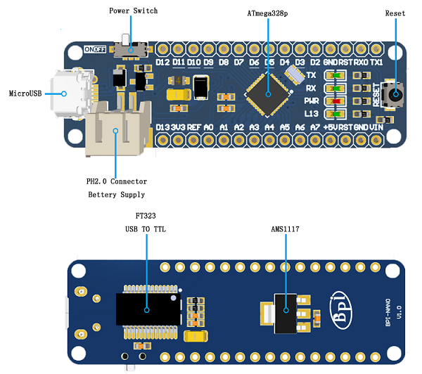
Hardware interface
Hardware spec
| Banana Pi BP-Nano | |||
| Microcontroller | ATmega328P | ||
| Operating Voltage | 5V | ||
| Input Voltage: (recommended) | 7-12V | ||
| Input Voltage: (limits) | 6-20V | ||
| Digital I/O Pins | 14(include 6 PWM output) | ||
| PWM PIN | 6个 | ||
| Analog Input Pins | 6个 | ||
| I/O output Max | 20mA | ||
| 3.3V output Max | 50mA | ||
| Flash | 32KB(ATmega328P) and 0.5KB used by bootloader | ||
| SRAM | 2KB(ATmega328P) | ||
| EEPROM | 1KB(ATmega328P) | ||
| Clock Speed | 16MHz | ||
| onboard LED | 13 | ||
| size | same as arduino NANO | ||
There is a self-restoring fuse on the bpi-uno that automatically disconnects the power supply when short-circuiting or overcurrent exceeds 500mA, thus protecting the USB port and bpi-uno of the computer. While most computer USB ports provide internal protection, this fuse provides additional protection.
Power
BPI-NANO can power with MicroUSB port,PH2.0 port and VIN port.
Power dependent pins are as follows:
- PH2.0 port: can input 7-12V,It can be controlled by a power switch。
- 5V:5V power PIN。when use USB power,direct output USB supplied 5V voltage;When using external power supply, output 5V voltage after voltage stabilization压。
- 3V3:3.3V power output PIN。output Max is 50 mA。
- VIN:Connect to external dc 5V power supply
- REF:I/O reference voltage. Other devices can identify the development board I/O reference voltage through this pin。
Note:FT232RL will only work if it is powered through the USB port。
Input and Output
Each of the 14 digital pins on the Nano can be used as an input or output, using pinMode(), digitalWrite(), and digitalRead() functions. They operate at 5 volts. Each pin can provide or receive a maximum of 40 mA and has an internal pull-up resistor (disconnected by default) of 20-50 kOhms. In addition, some pins have specialized functions: Serial: 0 (RX) and 1 (TX). Used to receive (RX) and transmit (TX) TTL serial data. These pins are connected to the corresponding pins of the FTDI USB-to-TTL Serial chip. External Interrupts: 2 and 3. These pins can be configured to trigger an interrupt on a low value, a rising or falling edge, or a change in value. See the attachInterrupt() function for details.
Some of them have special functions and these pins are as follows:
- Serial:0(RX)、1(TX),Used to receive (RX) and transmit (TX) TTL serial data. These pins are connected to the corresponding pins of the FTDI USB-to-TTL Serial chip。
- xternal Interrupts: 2 and 3. These pins can be configured to trigger an interrupt on a low value, a rising or falling edge, or a change in value
- PWM output:BPI-NANO have 3, 5, 6, 9, 10, and 11. Provide 8-bit PWM output with the analogWrite() function.
- SPI:10(SS)、11(MOSI)、12(MISO)、13(SCK),These pins support SPI communication, which, although provided by the underlying hardware, is not currently included in the Arduino language。
- L13:There is a built-in LED connected to digital pin 13. When the pin is HIGH value, the LED is on, when the pin is LOW, it's off.。
- I2C: 4 (SDA) and 5 (SCL). Support I2C (TWI) communication using the Wire library (documentation on the Wiring website).
BPI-NANO have 6 analog inputs, each of which provide 10 bits of resolution (i.e. 1024 different values). By default they measure from ground to 5 volts, though is it possible to change the upper end of their range using the analogReference() function. Additionally, some pins have specialized functionality:
There are a couple of other pins on the board:
- REF:Reference voltage for the analog inputs. Used with analogReference().
- Rst:Bring this line LOW to reset the microcontroller. Typically used to add a reset button to shields which block the one on the board.
LED
BPI-NANO have 4 LED,The effects are as follows:
- ON:Power indicator.When the bpi-nano is powered ON, the ON light comes ON
- TX:Serial transmission indicator. When connected to a computer using USB and the bpi-nano transmits data to the computer, the TX lights up
- RX:Serial receiving indicator. The RX lights up when the USB is connected to the computer and the bpi-nano receives data from the computer.
- L13:Programmable control indicator. The LED is connected to pin 13 of the bpi-nano through a special circuit. When pin 13 is in a high level or high resistance state, the LED will be lit up. When the electricity is low, it will not be lit up. The LED can be turned on and off by program or external input signal.
Communication
BPI-NANO has a number of facilities for communicating with a computer, another Arduino, or other microcontrollers. The ATmega168 and ATmega328 provide UART TTL (5V) serial communication, which is available on digital pins 0 (RX) and 1 (TX). An FTDI FT232RL on the board channels this serial communication over USB and the FTDI drivers (included with the Arduino software) provide a virtual com port to software on the computer. The Arduino software includes a serial monitor which allows simple textual data to be sent to and from the Arduino board. The RX and TX LEDs on the board will flash when data is being transmitted via the FTDI chip and USB connection to the computer (but not for serial communication on pins 0 and 1).
A SoftwareSerial library allows for serial communication on any of the Nano's digital pins.
The ATmega168 and ATmega328 also support I2C (TWI) and SPI communication. The Arduino software includes a Wire library to simplify use of the I2C bus; see the documentation for details. To use the SPI communication, please see the ATmega168 or ATmega328 datasheet.
Automatic (Software) Reset
Rather then requiring a physical press of the reset button before an upload, the Arduino Nano is designed in a way that allows it to be reset by software running on a connected computer. One of the hardware flow control lines (DTR) of the FT232RL is connected to the reset line of the ATmega168 or ATmega328 via a 100 nanofarad capacitor. When this line is asserted (taken low), the reset line drops long enough to reset the chip. The Arduino software uses this capability to allow you to upload code by simply pressing the upload button in the Arduino environment. This means that the bootloader can have a shorter timeout, as the lowering of DTR can be well-coordinated with the start of the upload.
This setup has other implications. When the Nano is connected to either a computer running Mac OS X or Linux, it resets each time a connection is made to it from software (via USB). For the following half-second or so, the bootloader is running on the Nano. While it is programmed to ignore malformed data (i.e. anything besides an upload of new code), it will intercept the first few bytes of data sent to the board after a connection is opened. If a sketch running on the board receives one-time configuration or other data when it first starts, make sure that the software with which it communicates waits a second after opening the connection and before sending this data.
Arduino Software
Arduino IDE
You can program the PI-NANO through Arduino IDE。
On the BPI-Nano using ATmega328 chip, there is a bootloader program stored, allowing users to upload the program to the development board, without the need for additional programmers. The process of uploading the program was completed using the STK500 protocol.
You can also upload the program to bpi-uno via the ICSP interface without using bootloader
Arduino driver install
- 1,Windows10 :Windows10 Plug in BPI-Nano and the driver will be installed automatically
- 2,Windows7 :
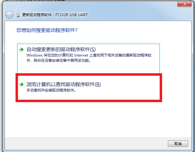
After plugging in bpi-uno, the system will try to install the driver automatically. If the installation fails, it will display, "failed to install the driver device successfully". In this case, the driver can be installed manually: Right click on "my computer", device manager, other devices; Right click on "unknown device" and click "update driver software" :
Select the second item, "browse the computer to find driver software";
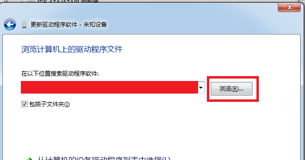
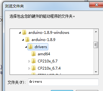
Click browse and select the driver address, which is the location of the driver in the ArduinoIDE you downloaded:
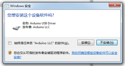
If the following prompt appears during installation, select "install" :
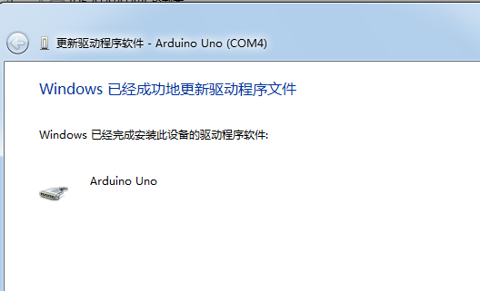
System prompt: driver installed successfully:
In the device manager, you can see the COM port for Arduino:
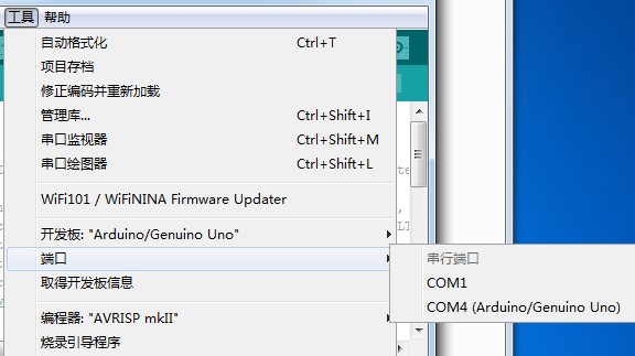
then you can find COM port in Arduino IDE
now, you can program with the Arudino IDE.
The resources
- Schematic diagram download :
- DXF file download:
- Guide:https://www.arduino.cc/en/Guide/ArduinoNano
Easy to buy sample
- BPI aliexpress shop : https://www.aliexpress.com/item/4000161897931.html
- BPI taobao shop : https://item.taobao.com/item.htm?ft=t&id=602561826873
- Welcome for OEM&ODM

