Difference between revisions of "BPI:bit robot expansion board"
(→Resources) |
|||
| (29 intermediate revisions by 2 users not shown) | |||
| Line 1: | Line 1: | ||
| − | [[File:BPI- | + | [[zh:BPI:bit robot 机器人扩展板]] |
| − | [[File: | + | [[File:BPI-bit_robort_board_3.JPG|thumb|[[BPI-Bit]] robot board ]] |
| − | [[File: | + | [[File:BPI-bit_robort_board_5.JPG|thumb|[[BPI-Bit]] robot board with [[BPI-Bit]]]] |
| + | [[File:BPI-bit_robort_board_2.JPG|thumb|[[BPI-Bit]] robot board also can use with Micro:bit]] | ||
| + | |||
| + | =About BPI:bit robot extension board = | ||
| + | BPI:bit robot extension board is a bpi-bit development board, which is mainly designed for smart cars and robots with bit as the core.At the same time, it also takes into account the ordinary IO extension function, which makes it convenient for users to use their imagination and create possibilities | ||
| + | |||
| + | *'''Support BPI:bit and Micro:bit''' | ||
| + | |||
| + | =Hardware= | ||
| + | |||
| + | ==BPI:bit robot extended board power supply== | ||
| + | |||
| + | The extended edition, there are two kinds of power-supply modes, 12V/2A dc power supply and Micro USB via 5V/2A power adapter power supply | ||
| + | |||
| + | *1,only use the extension board IO extension function , not use instead of dc motor and servo motor, you can use 5V Micro USB power supply directly | ||
| + | *2,if you want use dc motor and servo motor, you must use must use 12V dc supply. | ||
| + | |||
| + | ==Dc motor and steering engine== | ||
| + | |||
| + | the BPI:bit robot extension board has (MOTOR A-MOTOR D)4 sets of 8 MOTOR controls, which Can control four dc motor forward and reverse rotation and eight dc motor one-way rotation. | ||
| + | |||
| + | At the same time, four standard steering engine interfaces are designed on the extended version to control four servo motors at the same time.The control signal of dc motor and steering engine is chip (PCA9685) extended by the IIC bus interface. The motor interface use the extended PWM interface, which does not conflict with the sensor interface,Not use BPI:bit board resource valuable digital IO interface.At the same time, IIC bus supports address selection and can be used by multiple devices simultaneously.Dc motor drive circuit is designed with TB6612 dual-h bridge drive, and servo motor is designed with optocoupler isolation circuit to ensure the safety of the extended board and BPI:bit development board. However, due to component characteristics, the rated total current of dc motor and steering engine should not exceed 2A, and the power adapter should be equipped with 12V/3A dc power supply. | ||
| + | |||
| + | ==other extension interface== | ||
| + | |||
| + | A set of ultrasonic interfaces is designed at the bottom of the extended version, which USES a pin as, and can also be configured as a communication serial port (not a debug serial port).There are a total of 7 sets of 3 PIN base on both sides of the board, corresponding to the 3P interface socket of standard sensor designed for user convenience to carry out custom extension.At the same time, another set of 3P, 4P and 6P sockets are designed in the middle right of the extended version, in which the 3P socket is the extension BIT board button, which can be triggered by signals to achieve the purpose of simulating manual operation of keys.The 4P socket extends the interface for the IIC bus, because its features can involve more devices.The socket of 6P is the SPI bus extension interface of BIT board, which is also reserved for user's choice. | ||
| + | |||
| + | ==Hardware interface== | ||
| + | [[File:BPI-bit_robot_baord_interface.JPG]] | ||
| + | |||
| + | ==schematic diagram== | ||
| + | |||
| + | |||
| + | ==sample code== | ||
| + | |||
| + | * 1,Banana Pi BPI:bit robot board serve motor control test | ||
| + | ::video demo: https://www.youtube.com/watch?v=x2TzoumeH7A&feature=youtu.be | ||
| + | ::Arduino code:https://github.com/BPI-STEAM/BPI-BIT-Arduino-IDE/tree/master/example/SERVO | ||
| + | ::Platform IO code:https://github.com/BPI-STEAM/BPI-BIT-PlatformIO/tree/master/code/SERVO | ||
| + | |||
| + | * 2,Banana Pi BPI:bit robot board DC motor control test | ||
| + | ::video demo :https://www.youtube.com/watch?v=QK-5zq1MtME | ||
| + | ::Arduino code:https://github.com/BPI-STEAM/BPI-BIT-Arduino-IDE/blob/master/example/MOTOR/README.md | ||
| + | ::Platform IO code:https://github.com/BPI-STEAM/BPI-BIT-PlatformIO/blob/master/code/MOTOR/README.md | ||
| + | |||
| + | =Resources= | ||
| + | *easy to buy sample : https://pt.aliexpress.com/store/product/Banana-PI-bit-robot-extension-board-for-smart-cars-and-robots/302756_32957180207.html?spm=a2g03.12010612.8148356.9.19e7599egjDLj7 | ||
Latest revision as of 21:59, 28 November 2018


Contents
About BPI:bit robot extension board
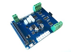
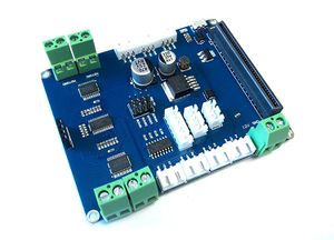
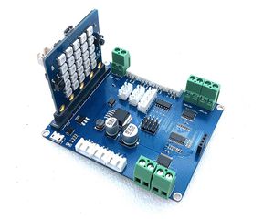
BPI:bit robot extension board is a bpi-bit development board, which is mainly designed for smart cars and robots with bit as the core.At the same time, it also takes into account the ordinary IO extension function, which makes it convenient for users to use their imagination and create possibilities
- Support BPI:bit and Micro:bit
Hardware
BPI:bit robot extended board power supply
The extended edition, there are two kinds of power-supply modes, 12V/2A dc power supply and Micro USB via 5V/2A power adapter power supply
- 1,only use the extension board IO extension function , not use instead of dc motor and servo motor, you can use 5V Micro USB power supply directly
- 2,if you want use dc motor and servo motor, you must use must use 12V dc supply.
Dc motor and steering engine
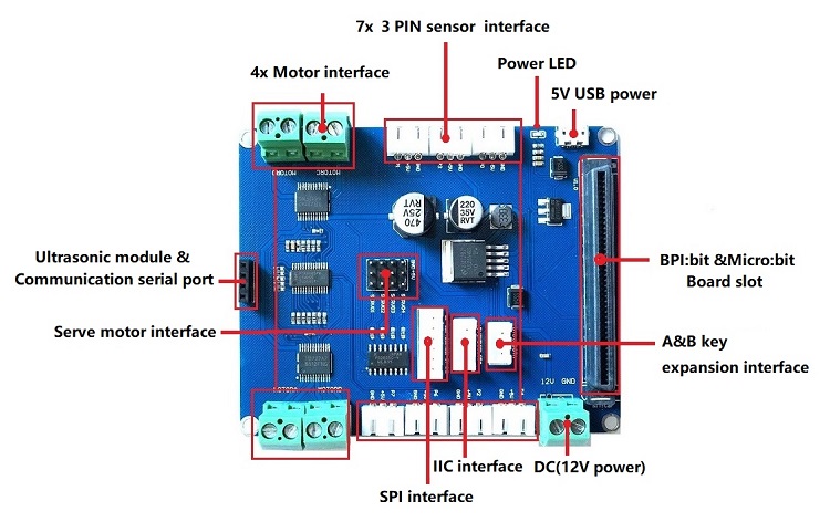
the BPI:bit robot extension board has (MOTOR A-MOTOR D)4 sets of 8 MOTOR controls, which Can control four dc motor forward and reverse rotation and eight dc motor one-way rotation.
At the same time, four standard steering engine interfaces are designed on the extended version to control four servo motors at the same time.The control signal of dc motor and steering engine is chip (PCA9685) extended by the IIC bus interface. The motor interface use the extended PWM interface, which does not conflict with the sensor interface,Not use BPI:bit board resource valuable digital IO interface.At the same time, IIC bus supports address selection and can be used by multiple devices simultaneously.Dc motor drive circuit is designed with TB6612 dual-h bridge drive, and servo motor is designed with optocoupler isolation circuit to ensure the safety of the extended board and BPI:bit development board. However, due to component characteristics, the rated total current of dc motor and steering engine should not exceed 2A, and the power adapter should be equipped with 12V/3A dc power supply.
other extension interface
A set of ultrasonic interfaces is designed at the bottom of the extended version, which USES a pin as, and can also be configured as a communication serial port (not a debug serial port).There are a total of 7 sets of 3 PIN base on both sides of the board, corresponding to the 3P interface socket of standard sensor designed for user convenience to carry out custom extension.At the same time, another set of 3P, 4P and 6P sockets are designed in the middle right of the extended version, in which the 3P socket is the extension BIT board button, which can be triggered by signals to achieve the purpose of simulating manual operation of keys.The 4P socket extends the interface for the IIC bus, because its features can involve more devices.The socket of 6P is the SPI bus extension interface of BIT board, which is also reserved for user's choice.
Hardware interface
schematic diagram
sample code
- 1,Banana Pi BPI:bit robot board serve motor control test
- 2,Banana Pi BPI:bit robot board DC motor control test

