Difference between revisions of "香蕉派 BPI-P2 Zero"
(→Resources) |
|||
| (13 intermediate revisions by the same user not shown) | |||
| Line 1: | Line 1: | ||
[[en:Banana_Pi_BPI-P2_Zero]] | [[en:Banana_Pi_BPI-P2_Zero]] | ||
| − | |||
=BPI-P2 Zero介绍= | =BPI-P2 Zero介绍= | ||
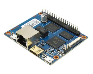
[[File:BPI-F2_zero_1.JPG|thumb|Overview BPI-F2 Zero with Allwinner H2+ chip]] | [[File:BPI-F2_zero_1.JPG|thumb|Overview BPI-F2 Zero with Allwinner H2+ chip]] | ||
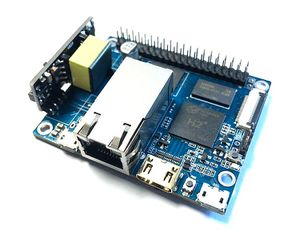
[[File:BPI-F2_zero_2.JPG|thumb|Overview BPI-F2 zero PoE support]] | [[File:BPI-F2_zero_2.JPG|thumb|Overview BPI-F2 zero PoE support]] | ||
| + | [[File:BPI-M2_zero_11.JPG|thumb|[[Banana Pi BPI-M2 ZERO]] with Allwinner H2+ chip]] | ||
[[File:BPI-9600_POE_4.JPG|thumb|Banana Pi BPI-P2 Zero with BPI-9600 POE module]] | [[File:BPI-9600_POE_4.JPG|thumb|Banana Pi BPI-P2 Zero with BPI-9600 POE module]] | ||
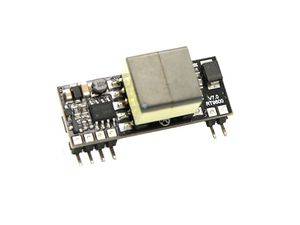
| − | [[File: | + | [[File:BPi-9600 Poe 4.jpg|thumb|[[BPI-9600 IEEE 802.3af PoE module]]]] |
[[File:Newwork_scu.JPG|thumb|BPI-4.0 OEM&ODM [[Successful case]] H3 for Network security information analysis instrument]] | [[File:Newwork_scu.JPG|thumb|BPI-4.0 OEM&ODM [[Successful case]] H3 for Network security information analysis instrument]] | ||
| Line 13: | Line 13: | ||
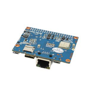
香蕉派 BPI-P2 Zero 四核开源物联网开发板,采用全志H2+芯片设计,也可以直接用在H3,H5芯片方案。Banana Pi BPI-P2 Zero 是一种小巧的物联网开发板,板子尺寸只有65毫米52.5毫米。它使用四核 H2+处理器(也可以选择全志H3和H5),有512 MB内存。8 G eMMC,100兆网口,支持PoE功能,wifi无线支持,它支持linux和android操作系统。 | 香蕉派 BPI-P2 Zero 四核开源物联网开发板,采用全志H2+芯片设计,也可以直接用在H3,H5芯片方案。Banana Pi BPI-P2 Zero 是一种小巧的物联网开发板,板子尺寸只有65毫米52.5毫米。它使用四核 H2+处理器(也可以选择全志H3和H5),有512 MB内存。8 G eMMC,100兆网口,支持PoE功能,wifi无线支持,它支持linux和android操作系统。 | ||
| − | [[File: | + | [[File:Banana_Pi_BPI-P2_zero.jpg]] |
==关键特性== | ==关键特性== | ||
| Line 27: | Line 27: | ||
==开始使用== | ==开始使用== | ||
| − | + | *镜像烧录及快速开始使用 : [[快速上手 香蕉派镜像烧录与系统启动]] | |
::如何使用BPI-P2 Zero开发 : [[Getting Start with M2 Zero]] | ::如何使用BPI-P2 Zero开发 : [[Getting Start with M2 Zero]] | ||
| Line 40: | Line 40: | ||
==硬件接口== | ==硬件接口== | ||
| − | [[File:BPI- | + | [[File:BPI-P2_zero_interface.jpg]] |
==硬件规格== | ==硬件规格== | ||
| Line 74: | Line 74: | ||
| Audio Output || Mini HDMI ||Mini HDMI ||Mini HDMI | | Audio Output || Mini HDMI ||Mini HDMI ||Mini HDMI | ||
|- | |- | ||
| − | | | + | | 供电|| Micro USB with 5V/2A or PoE power||Micro USB with 5V/2A ||5V/2A |
|- | |- | ||
| USB 2.0 Ports || one USB 2.0 OTG ||one USB 2.0 OTG ||one USB 2.0 OTG | | USB 2.0 Ports || one USB 2.0 OTG ||one USB 2.0 OTG ||one USB 2.0 OTG | ||
|- | |- | ||
| − | | | + | | 按键 || Power Button, Reset Button ||Power Button, Reset Button ||Composite video and reset headers |
|- | |- | ||
| Low-level peripherals || 40 Pins Header,compatible with Raspberry Pi 3 ||40 Pins Header,compatible with Raspberry Pi 3 ||40 PIN | | Low-level peripherals || 40 Pins Header,compatible with Raspberry Pi 3 ||40 Pins Header,compatible with Raspberry Pi 3 ||40 PIN | ||
| Line 84: | Line 84: | ||
| uart GPIO\(1x3\) pin || UART, ground ||UART, ground ||UART | | uart GPIO\(1x3\) pin || UART, ground ||UART, ground ||UART | ||
|- | |- | ||
| − | | | + | | LED灯 ||Power led & Status led|| Power led & Status led ||Power Status LED |
|- | |- | ||
| − | | | + | | IR红外控制 ||N/A|| N/A ||N/A |
|- | |- | ||
| − | | | + | | 支持系统 ||android linux|| android linx|| Linux |
|- | |- | ||
| − | | | + | | 产品尺寸 || 65mm X 52.5mm||65mm × 30mm ||65mm x 30mm |
|- | |- | ||
| − | | | + | | 重量 ||30g|| 15g ||9g |
|- | |- | ||
|} | |} | ||
| Line 98: | Line 98: | ||
==GPIO 定义 == | ==GPIO 定义 == | ||
| − | + | 香蕉派 BPI-P2 zero GPIO 定义与BPI-M2 Zero 完全一样 ,有40-pin GPIO 接口,定义兼容Raspberry Pi 3. 具体定义如下图所示: | |
[[File:Gpio define.png]] | [[File:Gpio define.png]] | ||
| Line 104: | Line 104: | ||
{| class="wikitable" | {| class="wikitable" | ||
|- | |- | ||
| − | | style="background: PaleTurquoise; color: black" colspan="4"| ''' | + | | style="background: PaleTurquoise; color: black" colspan="4"| '''香蕉派 BPI-P2 Zero 40 PIN GPIO定义''' |
|- | |- | ||
| GPIO Pin Name || Default Function || Function2:GPIO || Function3 | | GPIO Pin Name || Default Function || Function2:GPIO || Function3 | ||
| Line 279: | Line 279: | ||
** allwinner H3 chip doc baidu link: https://pan.baidu.com/s/1qTULll2CR02d0Hw9itq1rw | ** allwinner H3 chip doc baidu link: https://pan.baidu.com/s/1qTULll2CR02d0Hw9itq1rw | ||
** Allwinner H2+ chip doc baidu link: https://pan.baidu.com/s/1TGMYr3rhizfhlg5hl6hLyg | ** Allwinner H2+ chip doc baidu link: https://pan.baidu.com/s/1TGMYr3rhizfhlg5hl6hLyg | ||
| + | *BPI-P2 Zero 原理图:https://pan.baidu.com/s/1m66YYAAZVH_EpFSnBViFWw 提取码: urzs | ||
| + | *BPI-P2 Zero DXF 结构文件: https://drive.google.com/file/d/1NBenPRf6Pngsio930PKuzj6IqyUK5qyr/view?usp=sharing | ||
| + | *BPI-P2 zero CE,FCC,RoHS Certification : http://forum.banana-pi.org/t/banana-pi-bpi-p2-zero-ce-fcc-rohs-certification/9788 | ||
*Banana pi BPI-P2 Zero IEEE 802.3af PoE function test: https://www.youtube.com/watch?v=RCrDmhjxfCU&feature=youtu.be | *Banana pi BPI-P2 Zero IEEE 802.3af PoE function test: https://www.youtube.com/watch?v=RCrDmhjxfCU&feature=youtu.be | ||
| Line 289: | Line 292: | ||
:: kernel 3.4 source code : https://github.com/BPI-SINOVOIP/BPI-M2Z-bsp | :: kernel 3.4 source code : https://github.com/BPI-SINOVOIP/BPI-M2Z-bsp | ||
| − | = | + | =镜像发布= |
==Ubuntu == | ==Ubuntu == | ||
Latest revision as of 20:25, 11 July 2022
Contents
BPI-P2 Zero介绍
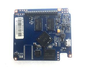
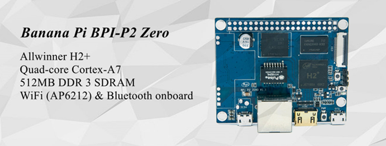
香蕉派 BPI-P2 Zero 四核开源物联网开发板,采用全志H2+芯片设计,也可以直接用在H3,H5芯片方案。Banana Pi BPI-P2 Zero 是一种小巧的物联网开发板,板子尺寸只有65毫米52.5毫米。它使用四核 H2+处理器(也可以选择全志H3和H5),有512 MB内存。8 G eMMC,100兆网口,支持PoE功能,wifi无线支持,它支持linux和android操作系统。
关键特性
- CPU: Allwinner H2+, Quad-core Cortex-A7.
- 512MB DDR 3 SDRAM.
- WiFi (AP6212) & Bluetooth onboard.
- Mini HDMI.
- 40 PIN GPIO,It includes UART, SPI, I2C, IO etc
- 100M LAN
- IEEE 802.3af PoE standard PoE module support
- 8G eMMC flash onboard.
开始使用
- 镜像烧录及快速开始使用 : 快速上手 香蕉派镜像烧录与系统启动
- 如何使用BPI-P2 Zero开发 : Getting Start with M2 Zero
硬件
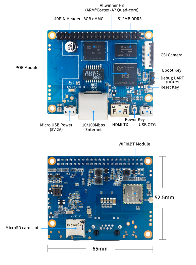
BPI-P2 Zero开发板,相比较BPI-M2 Zero .仅仅有三个地方有硬件改动,其他设计是一样的.所以最新软件镜像可以通用.
- 1,增加了板载8G eMMC flash,软件可以烧录在eMMC上,可以直接应用做IoT物联网产品.
- 2,BPI-P2 Zero 加了100兆有线网口 ,BPI-M2 Zero 有线网口只能用PIN针扩展,但软件使用方法一样.
- 3,增加了PoE网线供电功能.
硬件接口
硬件规格
| HardWare Specification of Banana pi BPI-P2 Zero VS BPI-M2 zero VS Raspberry Pi Zero W | |||
| 型号 | Banana Pi BPI-P2 Zero | Banana Pi BPI-M2 Zero | Raspberry Pi Zero W |
| CPU主控 | H2+ Quad-core Cortex-A7 H265/HEVC 1080P | H2+ Quad-core Cortex-A7 H265/HEVC 1080P | Broadcom BCM2835 32 Bit 1 GHz ARM1176JZF-S single-core |
| GPU | Mali400MP2 GPU @600MHz,Supports OpenGL ES 2.0 | Mali400MP2 GPU @600MHz,Supports OpenGL ES 2.0 | VideoCore IV |
| Memory \(SDRAM\) | 512M DDR3(shared with GPU) | 512M DDR3(shared with GPU) | 512 MB DDR2 |
| Onboard Storage | TF card \(Max. 64GB\) | TF card \(Max. 64GB\) | TF card \(Max. 64GB\) |
| 有线网络 | 100M LAN | NOPE (but can extension with PIN define) | NOPE |
| PoE 网线供电 | PoE function support | NOPE | NOPE |
| Onboard flash | 8G eMMC | NOPE | NOPE |
| WIFI无线 | SDIO AP6212(option AP6181、AP6335) | SDIO AP6212(option AP6181、AP6335) | 802.11n wireless, Bluetooth 4.1 |
| Video decoding | 1080p@60fps,H.264 Video encoding 1080p@30fps,H.264 | 1080p@60fps,H.264 Video encoding 1080p@30fps,H.264 | 1080p30 H.264/MPEG-4 AVC high-profile decoder and encoder |
| Video input | A CSI input connector Camera | A CSI input connector Camera | CSI camera connector |
| Video Outputs | mini HDMI 1.4,1080P@30fps, DHCP | mini HDMI 1.4,1080P@30fps, DHCP | Mini HDMI and USB On-The-Go ports |
| Audio Output | Mini HDMI | Mini HDMI | Mini HDMI |
| 供电 | Micro USB with 5V/2A or PoE power | Micro USB with 5V/2A | 5V/2A |
| USB 2.0 Ports | one USB 2.0 OTG | one USB 2.0 OTG | one USB 2.0 OTG |
| 按键 | Power Button, Reset Button | Power Button, Reset Button | Composite video and reset headers |
| Low-level peripherals | 40 Pins Header,compatible with Raspberry Pi 3 | 40 Pins Header,compatible with Raspberry Pi 3 | 40 PIN |
| uart GPIO\(1x3\) pin | UART, ground | UART, ground | UART |
| LED灯 | Power led & Status led | Power led & Status led | Power Status LED |
| IR红外控制 | N/A | N/A | N/A |
| 支持系统 | android linux | android linx | Linux |
| 产品尺寸 | 65mm X 52.5mm | 65mm × 30mm | 65mm x 30mm |
| 重量 | 30g | 15g | 9g |
GPIO 定义
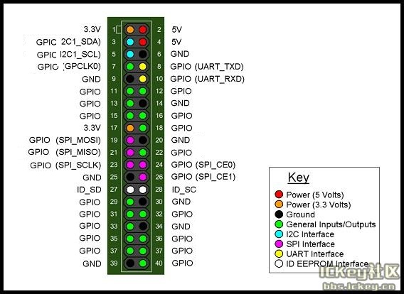
香蕉派 BPI-P2 zero GPIO 定义与BPI-M2 Zero 完全一样 ,有40-pin GPIO 接口,定义兼容Raspberry Pi 3. 具体定义如下图所示:
| 香蕉派 BPI-P2 Zero 40 PIN GPIO定义 | |||
| GPIO Pin Name | Default Function | Function2:GPIO | Function3 |
| CON2-P01 | VCC-3V3 | ||
| CON2-P02 | VCC-5V | ||
| CON2-P03 | TWI0-SDA | PA12-EINT12 | |
| CON2-P04 | VCC-5V | ||
| CON2-P05 | TWI0-SCK | PA11-EINT11 | |
| CON2-P06 | GND | ||
| CON2-P07 | PWM1 | PA6-EINT6 | |
| CON2-P08 | UART3-TX | PA13-EINT13 | SPI1-CS |
| CON2-P09 | GND | ||
| CON2-P10 | UART3-RX | PA14-EINT14 | SPI1-CLK |
| CON2-P11 | UART2-RX | PA1-EINT1 | |
| CON2-P12 | UART3-CTS | PA16-EINT16 | SPI1-MISO |
| CON2-P13 | UART2-TX | PA0-EINT0 | |
| CON2-P14 | GND | ||
| CON2-P15 | UART2-CTS | PA3-EINT3 | |
| CON2-P16 | UART3-RTS | PA15-EINT15 | SPI1-MOSI |
| CON2-P17 | VCC-3V3 | ||
| CON2-P18 | PC4 | PC4 | |
| CON2-P19 | SPI0-MOSI | PC0 | |
| CON2-P20 | GND | ||
| CON2-P21 | SPI0-MISO | PC1 | |
| CON2-P22 | UART2-RTS | PA2-EINT2 | |
| CON2-P23 | SPI0-CLK | PC2 | |
| CON2-P24 | SPI0-CS | PC3 | |
| CON2-P25 | GND | ||
| CON2-P26 | PC7 | PC7 | |
| CON2-P27 | TWI1-SDA | PA19-EINT19 | |
| CON2-P28 | TWI1-SCK | PA18-EINT18 | |
| CON2-P29 | PA7-EINT7 | PA7-EINT7 | |
| CON2-P30 | GND | ||
| CON2-P31 | PA8-EINT8 | PA8-EINT8 | |
| CON2-P32 | PL2-S-EINT2 | PL2-S-EINT2 | |
| CON2-P33 | PA9-EINT9 | PA9-EINT9 | |
| CON2-P34 | GND | ||
| CON2-P35 | PA10-EINT10 | PA10-EINT10 | |
| CON2-P36 | PL4-S-EINT4 | PL4-S-EINT4 | |
| CON2-P37 | PA17-EINT17 | PA17-EINT17 | SPDIF-OUT |
| CON2-P38 | PA21-EINT21 | PA21-EINT21 | |
| CON2-P39 | GND | ||
| CON2-P40 | PA20-EINT20 | PA20-EINT20 | |
CSI Camera Connector specification:
The CSI Camera Connector is a 24-pin FPC connector which can connect external camera module with proper signal pin mappings. The pin definitions of the CSI interface are shown as below. This is marked on the Banana Pi board as “CSI″.
| 24 PIN CSI Camera connector of Banana pi BPI-P2 Zero | |||
| CSI Pin Name | Default Function | Function2:GPIO | |
| CN3-P01 | NC | ||
| CN3-P02 | GND | ||
| CN3-P03 | CSI0-SDA | PE13 | |
| CN3-P04 | CSI0-AVDD | ||
| CN3-P05 | CSI0-SCK | PE12 | |
| CN3-P06 | CSI0-Reset | PE14 | |
| CN3-P07 | CSI0-VSYNC | PE3 | |
| CN3-P08 | CSI0-PWDN | PE15 | |
| CN3-P09 | CSI0-HSYNC | PE2 | |
| CN3-P10 | CSI0-DVDD | ||
| CN3-P11 | CSI0-DOVDD | ||
| CN3-P12 | CSI0-D7 | PE11 | |
| CN3-P13 | CSI0-MCLK | PE1 | |
| CN3-P14 | CSI0-D6 | PE10 | |
| CN3-P15 | GND | ||
| CN3-P16 | CSI0-D5 | PE9 | |
| CN3-P17 | CSI0-PCLK | PE0 | |
| CN3-P18 | CSI0-D4 | PE8 | |
| CN3-P19 | CSI0-D0 | PE4 | |
| CN3-P20 | CSI0-D3 | PE7 | |
| CN3-P21 | CSI0-D1 | PE5 | |
| CN3-P22 | CSI0-D2 | PE6 | |
| CN3-P23 | GND | ||
| CN3-P24 | CSI0-DOVDD | ||
UART specification:
The jumper CON3 is the UART interface. For developers of Banana Pi, this is an easy way to get the UART console output to check the system status and log message.
| jumper CON3 of Banana pi BPI-P2 Zero | |||
| CON3 Pin Name | Default Function | GPIO | |
| CON3 P03 | UART0-TXD | PA4 | |
| CON3 P02 | UART0-RXD | PA5 | |
| CON3 P01 | GND | ||
PoE 网线供电
we deign a IEEE 802.3af PoE module for BPI-P2 Zero ,easy to support PoE function,more spec ,please check BPI-9600 PoE module spec
资源
开发文档
- Allwinner documents:
- allwinner H3 chip doc baidu link: https://pan.baidu.com/s/1qTULll2CR02d0Hw9itq1rw
- Allwinner H2+ chip doc baidu link: https://pan.baidu.com/s/1TGMYr3rhizfhlg5hl6hLyg
- BPI-P2 Zero 原理图:https://pan.baidu.com/s/1m66YYAAZVH_EpFSnBViFWw 提取码: urzs
- BPI-P2 Zero DXF 结构文件: https://drive.google.com/file/d/1NBenPRf6Pngsio930PKuzj6IqyUK5qyr/view?usp=sharing
- BPI-P2 zero CE,FCC,RoHS Certification : http://forum.banana-pi.org/t/banana-pi-bpi-p2-zero-ce-fcc-rohs-certification/9788
- Banana pi BPI-P2 Zero IEEE 802.3af PoE function test: https://www.youtube.com/watch?v=RCrDmhjxfCU&feature=youtu.be
软件源代码
- Android 4.4 源代码
- Linux 源代码
- kernel 3.4 source code : https://github.com/BPI-SINOVOIP/BPI-M2Z-bsp
镜像发布
Ubuntu
- 2018-08-17 update Ubuntu image V1.0 release This release is for BPI-P2 Zero board which is based on Allwinner H2+, We have one demo image release,Ubuntu 16.04 is based on kernel 3.4.
- BPI-P2 Zero image Features Map : http://wiki.banana-pi.org/P2Z_Image_Map
- Google Drive : https://drive.google.com/open?id=1izY4ib2roA4I9s4psbXqZq5sBXLkCgBE
- Baidu Drive : https://pan.baidu.com/s/1-pAplB8_j_W5mUsYsinavg
- Forum pthread : http://forum.banana-pi.org/t/bananapi-bpi-p2-zero-h2-with-poe-ubuntu-image-release-2018-08-17/6533
