Difference between revisions of "Getting Started BPI-UNO32 with Visuino"
| (9 intermediate revisions by the same user not shown) | |||
| Line 1: | Line 1: | ||
| + | =About BPI-UNO32= | ||
| + | |||
| + | *BPI-UNO32 wiki : [[BPI-UNO32]] | ||
| + | |||
| + | =How to use BPI-UNO32 with Visuino= | ||
| + | |||
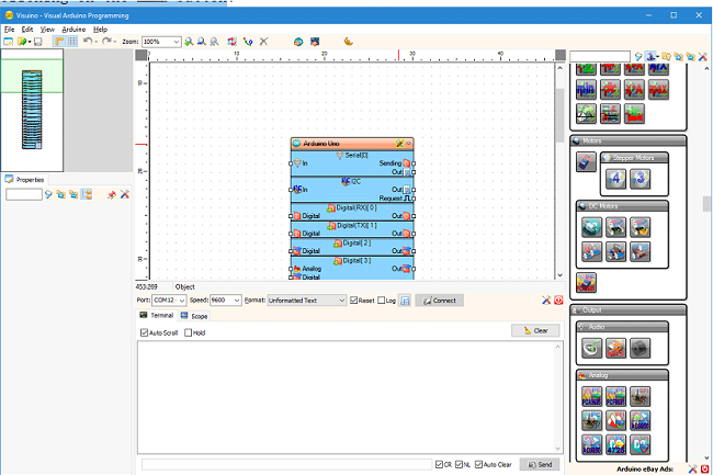
The BPI:UNO32 is fully supported in Visuino and can be selected as board by double clicking on the Arduino component in the design are, or by clicking on the button\ | The BPI:UNO32 is fully supported in Visuino and can be selected as board by double clicking on the Arduino component in the design are, or by clicking on the button\ | ||
| Line 10: | Line 16: | ||
[[File:Visuino_start_3.png]] | [[File:Visuino_start_3.png]] | ||
| + | |||
| + | Including the Hall Sensor, the Button, Buzzer, LED pins, and the Wi-Fi module: | ||
| + | |||
| + | [[File:Visuino_start_4.png]] | ||
| + | |||
| + | No as example, by simply connecting the Output of the Hall sensor to the Input of the Serial port, the BPI:UNO32 can be programmed to send the Hall Sensor values to the Serial Terminal: | ||
| + | |||
| + | [[File:Visuino_start_5.png]] | ||
| + | |||
| + | The Wi-Fi Module supports variety of operations, even including programming over the air (Wi-Fi). | ||
| + | |||
| + | Adding the operations is as simple as clicking on the “...”and [[File:Visuino_start_6.png]] button of the Operations property: | ||
| + | |||
| + | [[File:Visuino_start_7.png]] | ||
| + | |||
| + | And selecting the Operations to add: | ||
| + | |||
| + | [[File:Visuino_start_8.png]] | ||
| + | |||
| + | Once as example “Scan Networks” operation is added, it will appear on the BPI:UNO32 component and it can be connected, as example to print the SSIDs of the discovered hot-spots: | ||
| + | |||
| + | [[File:Visuino_start_9.png]] | ||
| + | |||
| + | Adding sockets is equally simple: | ||
| + | |||
| + | [[File:Visuino_start_10.png]] | ||
| + | |||
| + | [[File:Visuino_start_11.png]] | ||
| + | |||
| + | And once the sockets are added, they can be connected to send the data from any sensor, or control any actuator: | ||
| + | |||
| + | [[File:Visuino_start_12.png]] | ||
| + | |||
| + | All the Visuino components for sensors, displays, actuators, processing communication and more are available to be used with BPI:UNO32 as shown in this example displaying the Temperature and Humidity on OLED display, and controlling servo position based on the temperature: | ||
| + | |||
| + | [[File:Visuino_start_13.png]] | ||
| + | |||
| + | All currently supported shields are also available and can be added to the BPI:UNO32 component: | ||
| + | |||
| + | [[File:Visuino_start_14.png]] | ||
| + | |||
| + | [[File:Visuino_start_15.png]] | ||
| + | |||
| + | [[File:Visuino_start_16.png]] | ||
| + | |||
| + | And once added their functionality will appear on the component: | ||
| + | |||
| + | [[File:Visuino_start_17.png]] | ||
| + | |||
| + | Once a project is designed, by simply clicking on the [[File:Visuino_start_18.png]] button, Visuino will generate the necessary C++ code, and will open the Arduino IDE: | ||
| + | |||
| + | [[File:Visuino_start_19.png]] | ||
| + | |||
| + | In the Arduino IDE the generated code can be compiled and uploaded: | ||
| + | |||
| + | [[File:Visuino_start_20.png]] | ||
Latest revision as of 20:05, 6 June 2018
About BPI-UNO32
- BPI-UNO32 wiki : BPI-UNO32
How to use BPI-UNO32 with Visuino
The BPI:UNO32 is fully supported in Visuino and can be selected as board by double clicking on the Arduino component in the design are, or by clicking on the button\
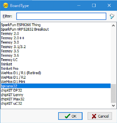
This will open a dialog listing all supported boards, and bpi:uno32 can be selected:
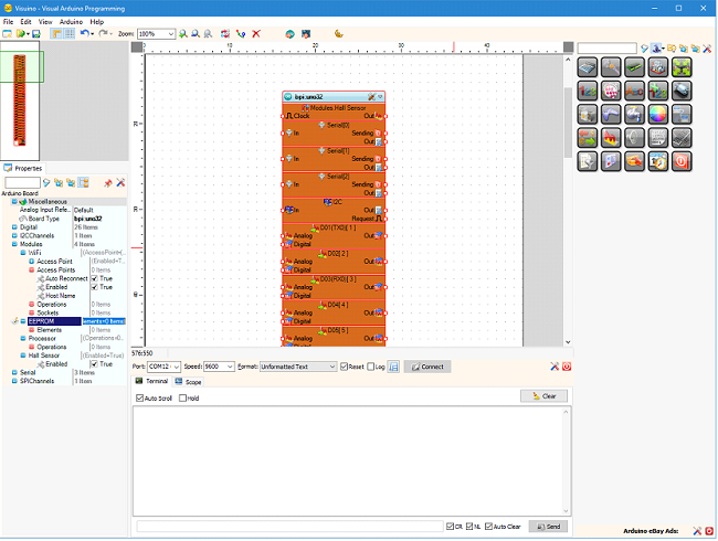
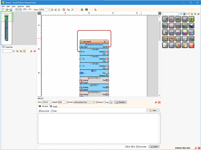
Once the board is selected the component in the design area will change to represent all the capabilities available on the BPI:UNO32:
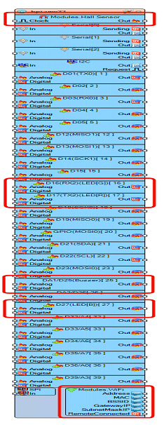
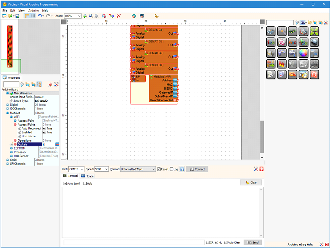
Including the Hall Sensor, the Button, Buzzer, LED pins, and the Wi-Fi module:
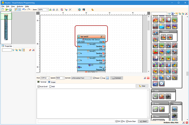
No as example, by simply connecting the Output of the Hall sensor to the Input of the Serial port, the BPI:UNO32 can be programmed to send the Hall Sensor values to the Serial Terminal:
The Wi-Fi Module supports variety of operations, even including programming over the air (Wi-Fi).
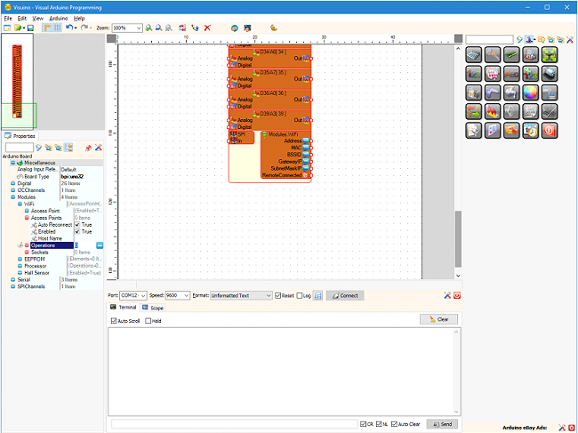
Adding the operations is as simple as clicking on the “...”and  button of the Operations property:
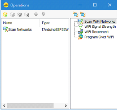
And selecting the Operations to add:
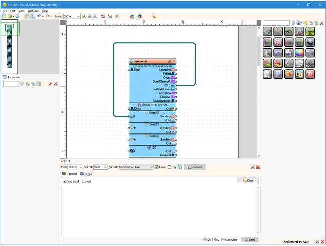
Once as example “Scan Networks” operation is added, it will appear on the BPI:UNO32 component and it can be connected, as example to print the SSIDs of the discovered hot-spots:
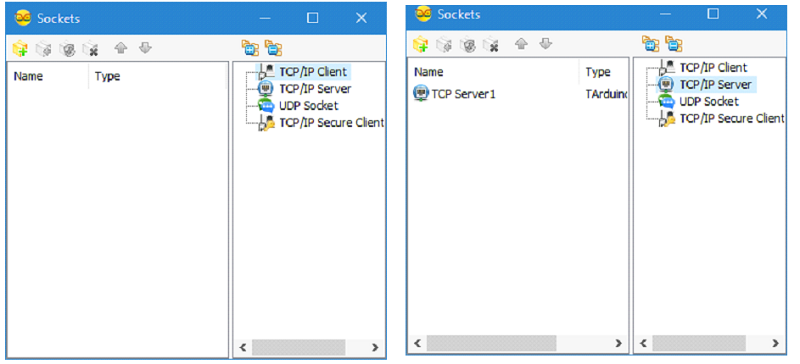
Adding sockets is equally simple:
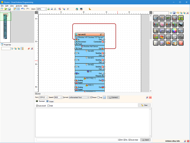
And once the sockets are added, they can be connected to send the data from any sensor, or control any actuator:
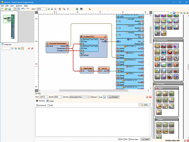
All the Visuino components for sensors, displays, actuators, processing communication and more are available to be used with BPI:UNO32 as shown in this example displaying the Temperature and Humidity on OLED display, and controlling servo position based on the temperature:
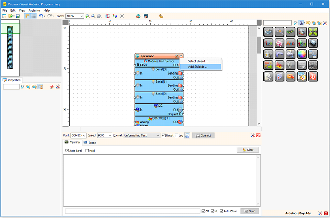
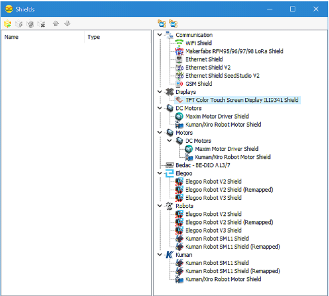
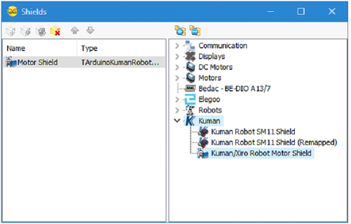
All currently supported shields are also available and can be added to the BPI:UNO32 component:
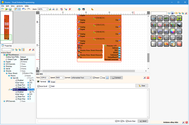
And once added their functionality will appear on the component:
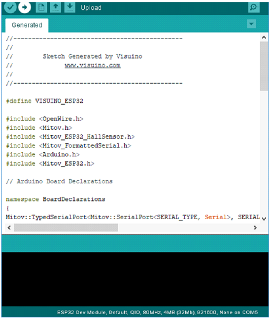
Once a project is designed, by simply clicking on the  button, Visuino will generate the necessary C++ code, and will open the Arduino IDE:
In the Arduino IDE the generated code can be compiled and uploaded:
