Difference between revisions of "BPI-PC101 gesture recognition module"
(→PIN definitions) |
(→Documents) |
||
| (46 intermediate revisions by the same user not shown) | |||
| Line 2: | Line 2: | ||
= Introduction= | = Introduction= | ||
| + | [[File:Pc101Gesture_Sensor_1_.jpg|thumb|Overview:PC101 Gesture_Sensor]] | ||
| + | [[File:Pc101_Gesture_Sensor_2.jpg|thumb|PC101 Gesture_Sensor]] | ||
| + | The PC101 integrates an ambient light (ALS) sensor, a proximity sensor (PS) and 6-D gesture | ||
| + | sensors with built-in IR LED. It is used in notebook PCs, smartphones, MIDs (mobile internet devices),PNDs (portable navigation devices), e-books, tablet PCs, flat-panel televisions, etc. for extending battery life and for better user experience. Ambient light sensor optimizes the screen brightness to extend battery and to increase battery life. Proximity sensor (PS) measures the IR reflection intensity which correlates to the distance of the object. Proximity sensor enables the device controller to turn off the LCD back-light and the touch-screen sensor when the device is held close to your ear, placed inside the pocket, purse, or bags. This function saves the battery power and avoids unintended touch-screen trigger. Proximity sensor can also work as a device wake-up sensor by sensing the user waving the hand in front of the device. The 6-D gesture sensor detects the waving of palm in front of the screen in 6 | ||
| + | directions left, right, up, down and z-axis. The hand gesture without the need to touch the screen adds new way of human device interaction. For example, the gesture can be used to accept a phone call in the hand-free mode while the user is driving in a car. In another example, the user wave to the screen to advance or retract in the picture viewing mode without worrying the food stains from the fingers to be left on the screen. | ||
| + | |||
| + | == Key Features == | ||
| + | *Digital control and data output via I2C (100 KHz and 400 KHz) interface | ||
| + | *ALS, PS and Gesture sensor with built-in IR LED | ||
| + | *Slave Address 0x58 | ||
| + | *6D Gesture Recognition Distance: 20~200 mm(up、down、left、right、hold) | ||
| + | *Programmable interrupt function for ALS and PS with upper and lower thresholds | ||
| + | *Support interrupt notification | ||
| + | |||
| + | ==Applications== | ||
| + | *smart lights | ||
| + | *Household electrical control | ||
| + | *Music control equipment | ||
| + | *Game equipment | ||
| + | *Smart bath | ||
| + | *Distance detection | ||
| + | *Smart toy | ||
= Hardware = | = Hardware = | ||
| + | ==Interface== | ||
| + | [[File:Pc101_interface.jpg]] | ||
| + | |||
| + | ==Block Diagram== | ||
| + | [[File:Pc101_block.png]] | ||
| + | |||
| + | ==PC101 DFN Pin Assignment== | ||
| + | |||
| + | [[File:Pc101_1.png]] | ||
| + | |||
| + | ==Hardware spec== | ||
| + | |||
| + | ==PC101 PIN definitions== | ||
| + | {| class="wikitable" | ||
| + | |- | ||
| + | | style="background: PaleTurquoise; color: black" colspan="4"| '''PC101 Gesture Sensor Pin define ''' | ||
| + | |- | ||
| + | |Pin || Name|| Description | ||
| + | |- | ||
| + | |1 ||5V || Power | ||
| + | |- | ||
| + | |2|| GND || Ground | ||
| + | |- | ||
| + | |3|| INT || Digital Out | ||
| + | |- | ||
| + | |4 || SCL || Serial Digital Input Clock | ||
| + | |- | ||
| + | |5|| SDA || Serial Digital I/O Data | ||
| + | |- | ||
| + | |6 ||TXD|| Serial port sends pins | ||
| + | |- | ||
| + | |7 ||RXD|| The serial port receives the pin | ||
| + | |- | ||
| + | |} | ||
| + | |||
| + | ==Application Circuit== | ||
| + | |||
| + | [[File:Pc101_2.png]] | ||
| + | |||
| + | ==Electrical Characteristics== | ||
| + | |||
| + | * Voltage characteristic | ||
| + | {| class="wikitable" | ||
| + | |- | ||
| + | | style="background: PaleTurquoise; color: black" colspan="4"| '''Voltage characteristic ''' | ||
| + | |- | ||
| + | |No || pin || MIN|| TYP || MAX || UNIT | ||
| + | |- | ||
| + | |1 || 5V || 4.5 || 5.0 || 5.5 || V | ||
| + | |- | ||
| + | |2|| GND || -0.3 || 0 ||0.3 || V | ||
| + | |- | ||
| + | |3|| INT || GND ||0/3.3|| 3.7 || V | ||
| + | |- | ||
| + | |4|| SCL || -0.3|| 0/3.3|| 3.7 || V | ||
| + | |- | ||
| + | |5|| SDA || -0.3 || 0/3.3 ||3.7 || V | ||
| + | |- | ||
| + | |} | ||
| + | |||
| + | *Digital interface characteristics | ||
| + | |||
| + | {| class="wikitable" | ||
| + | |- | ||
| + | | style="background: PaleTurquoise; color: black" colspan="4"| '''Digital interface characteristics ''' | ||
| + | |- | ||
| + | |No || Description ||MIN|| TYP|| MAX|| UNIT | ||
| + | |- | ||
| + | |1 || SCL/SDA:LOW || -0.3 || - || 1.0 || V | ||
| + | |- | ||
| + | |2 || SCL/SDA:HIGH || 2.3 || - || 3.6 || V | ||
| + | |- | ||
| + | |3 || SCL || 0 || - || 400 || kHz | ||
| + | |- | ||
| + | |4 || Pull-up resistors || - || 2.0 || - || kΩ | ||
| + | |- | ||
| + | |5 || INT:LOW ||- || - || 0.4 || V | ||
| + | |- | ||
| + | |6 || INT:HIGH ||2.4 || - || - || V | ||
| + | |- | ||
| + | |} | ||
| + | |||
| + | ==I2C interface== | ||
| + | |||
| + | {| class="wikitable" | ||
| + | |- | ||
| + | | style="background: PaleTurquoise; color: black" colspan="4"| ''I2C interface ''' | ||
| + | |- | ||
| + | |Ordering Chip Information ||Write to Slave ||Read from Slave | ||
| + | |- | ||
| + | |PC101 ||1011000 ||1011001 | ||
| + | |- | ||
| + | |} | ||
| + | |||
| + | *Receive (Single Read) data from register | ||
| + | |||
| + | [[File:Pc101_3.png]] | ||
| + | |||
| + | *Send (Single Write) data into register | ||
| + | |||
| + | [[File:Pc101_4.png]] | ||
| + | |||
| + | =Principles of Operation= | ||
| + | |||
| + | Total register addresses are maintained inside the I2C block, each having a 8-bit register address. Each address accommodates an 8-bit data register that can be either written or read via I2C. The command registers program the sensor for various modes, setting and Interrupt threshold. The read-only registers contains output codes. | ||
| + | |||
| + | *Register Table and Definitions | ||
| + | {| class="wikitable" | ||
| + | |- | ||
| + | | style="background: PaleTurquoise; color: black" colspan="4"| '''Register Table and Definitions''' | ||
| + | |- | ||
| + | |NAME ||R/W ||8-bit Address || Default || Descrition | ||
| + | |- | ||
| + | |ChipID || R || 0x00 || 0xAA || Chip ID | ||
| + | |- | ||
| + | |Capability|| R || 0x01 || 0xF0 || Gesture Functional description | ||
| + | |- | ||
| + | |LibVersion || R || 0x02 || 0xB1 || Gesture Version | ||
| + | |- | ||
| + | |Gesture || R || 0x03 || 0x00 || Gesture Data | ||
| + | |- | ||
| + | |Proximity || R || 0x04 || 0x00 || Distance | ||
| + | |- | ||
| + | |} | ||
| + | |||
| + | *0x00: ChipID | ||
| + | |||
| + | This address holds ChipID, which is 0xAA by default and can be read to verify that I2C reading is normal. | ||
| + | |||
| + | *0x01: Capability | ||
| + | |||
| + | This address holds a bitmap of the gesture detection capability, 0 Disable, 1 enable. | ||
| + | |||
| + | {| class="wikitable" | ||
| + | |- | ||
| + | | style="background: PaleTurquoise; color: black" colspan="4"| '''Digital interface characteristics ''' | ||
| + | |- | ||
| + | |BIT || 7 || 6 || 5 ||4 ||3 || 2 || 1 ||0 | ||
| + | |- | ||
| + | |Read || Proximity|| Hold|| Left/Right|| Up/Down|| Reserved|| Reserved|| Reserved|| Reserved | ||
| + | |- | ||
| + | |Reset|| 1 || 1 ||1 || 1|| 0 ||0|| 0|| 0 | ||
| + | |- | ||
| + | |} | ||
| + | The default is all supported, so the register defaults is 0xF0. | ||
| + | |||
| + | *0x02: LibVersion | ||
| + | |||
| + | This address holds Gesture Version defaults is 0xB1. | ||
| + | |||
| + | *0x03: Gesture Date | ||
| + | |||
| + | The address is stored with the result of gesture detection. | ||
| + | |||
| + | {| class="wikitable" | ||
| + | |- | ||
| + | | style="background: PaleTurquoise; color: black" colspan="4"| '''address of gesture detection ''' | ||
| + | |- | ||
| + | |0:|| Gesture(Hold) || 0xA0 | ||
| + | |- | ||
| + | |1:|| Gesture(Up)|| 0xA1 | ||
| + | |- | ||
| + | |2:|| Gesture(Down)|| 0xA2 | ||
| + | |- | ||
| + | |3:|| Gesture(Left)|| 0xA3 | ||
| + | |- | ||
| + | |4:|| Gesture(Right)|| 0xA4 | ||
| + | |- | ||
| + | |} | ||
| + | *0x04: Proximity Date | ||
| − | + | This address holds the distance of the gesture from 0 to 255, the larger is near, the smaller is far. | |
| − | == | + | =How to Start= |
| + | ==Use Uart== | ||
| + | [[File:Pc101_5.png]] | ||
| + | Connect product like the Circuit diagram , Set the Baud Rate as 115200 | ||
| + | [[File:Pc101_6.png]] | ||
| − | == | + | Using TTL-USB moudle, you can see the data like the picture |
| + | |||
| + | [[File:Pc101_7.png]] | ||
| + | |||
| + | ==Use I2C== | ||
| + | |||
| + | Connect product like the Circuit diagram | ||
| + | |||
| + | [[File:Pc101_8.png]] | ||
| + | |||
| + | Set the SlaveAddress as 0x58, | ||
| + | |||
| + | Read Register 0x00, and result is 0xAA. | ||
| + | |||
| + | So, the I2C communicate success. | ||
| + | |||
| + | *Plan one : Polling | ||
| + | |||
| + | Every 100ms read once gesture data. | ||
| + | |||
| + | Read Register 0x03, and result is Gesture data. | ||
| + | |||
| + | [[File:Pc101_9.png]] | ||
| + | |||
| + | *Plan two :Interrupt | ||
| + | Read once gesture data when trigger edge is falling edg. | ||
| − | + | Read Register 0x03, and result is Gesture data. | |
| + | [[File:Pc101_10.png]] | ||
| + | Need connect Pin INT. | ||
| − | = | + | =Documents= |
| − | + | *Discuss on forum : http://forum.banana-pi.org/t/banana-pi-bpi-pc101-gesture-recognition-module/5507 | |
| + | *Easy to buy sample : https://www.aliexpress.com/store/product/Banana-PI-PC101-Gesture-Recognition-Module/302756_32892011635.html?spm=2114.12010611.8148356.5.3a1c30d9Vlrr5B | ||
Latest revision as of 02:09, 28 June 2018
Introduction
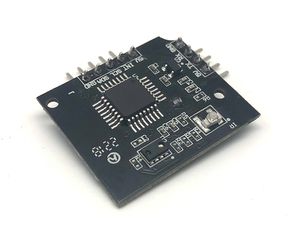
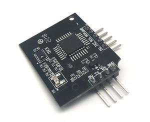
The PC101 integrates an ambient light (ALS) sensor, a proximity sensor (PS) and 6-D gesture sensors with built-in IR LED. It is used in notebook PCs, smartphones, MIDs (mobile internet devices),PNDs (portable navigation devices), e-books, tablet PCs, flat-panel televisions, etc. for extending battery life and for better user experience. Ambient light sensor optimizes the screen brightness to extend battery and to increase battery life. Proximity sensor (PS) measures the IR reflection intensity which correlates to the distance of the object. Proximity sensor enables the device controller to turn off the LCD back-light and the touch-screen sensor when the device is held close to your ear, placed inside the pocket, purse, or bags. This function saves the battery power and avoids unintended touch-screen trigger. Proximity sensor can also work as a device wake-up sensor by sensing the user waving the hand in front of the device. The 6-D gesture sensor detects the waving of palm in front of the screen in 6 directions left, right, up, down and z-axis. The hand gesture without the need to touch the screen adds new way of human device interaction. For example, the gesture can be used to accept a phone call in the hand-free mode while the user is driving in a car. In another example, the user wave to the screen to advance or retract in the picture viewing mode without worrying the food stains from the fingers to be left on the screen.
Key Features
- Digital control and data output via I2C (100 KHz and 400 KHz) interface
- ALS, PS and Gesture sensor with built-in IR LED
- Slave Address 0x58
- 6D Gesture Recognition Distance: 20~200 mm(up、down、left、right、hold)
- Programmable interrupt function for ALS and PS with upper and lower thresholds
- Support interrupt notification
Applications
- smart lights
- Household electrical control
- Music control equipment
- Game equipment
- Smart bath
- Distance detection
- Smart toy
Hardware
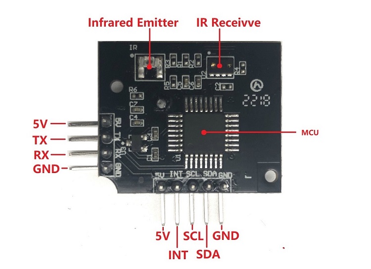
Interface
Block Diagram
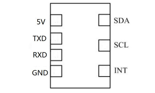
PC101 DFN Pin Assignment
Hardware spec
PC101 PIN definitions
| PC101 Gesture Sensor Pin define | |||
| Pin | Name | Description | |
| 1 | 5V | Power | |
| 2 | GND | Ground | |
| 3 | INT | Digital Out | |
| 4 | SCL | Serial Digital Input Clock | |
| 5 | SDA | Serial Digital I/O Data | |
| 6 | TXD | Serial port sends pins | |
| 7 | RXD | The serial port receives the pin | |
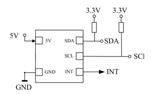
Application Circuit
Electrical Characteristics
- Voltage characteristic
| Voltage characteristic | |||||
| No | pin | MIN | TYP | MAX | UNIT |
| 1 | 5V | 4.5 | 5.0 | 5.5 | V |
| 2 | GND | -0.3 | 0 | 0.3 | V |
| 3 | INT | GND | 0/3.3 | 3.7 | V |
| 4 | SCL | -0.3 | 0/3.3 | 3.7 | V |
| 5 | SDA | -0.3 | 0/3.3 | 3.7 | V |
- Digital interface characteristics
| Digital interface characteristics | |||||
| No | Description | MIN | TYP | MAX | UNIT |
| 1 | SCL/SDA:LOW | -0.3 | - | 1.0 | V |
| 2 | SCL/SDA:HIGH | 2.3 | - | 3.6 | V |
| 3 | SCL | 0 | - | 400 | kHz |
| 4 | Pull-up resistors | - | 2.0 | - | kΩ |
| 5 | INT:LOW | - | - | 0.4 | V |
| 6 | INT:HIGH | 2.4 | - | - | V |
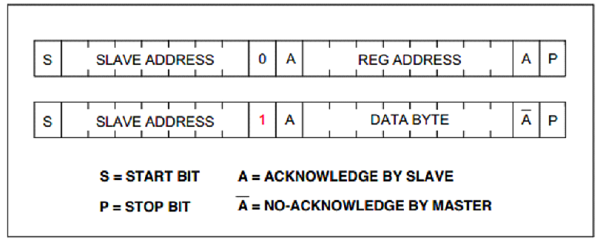
I2C interface
| I2C interface ' | |||
| Ordering Chip Information | Write to Slave | Read from Slave | |
| PC101 | 1011000 | 1011001 | |
- Receive (Single Read) data from register
- Send (Single Write) data into register
Principles of Operation
Total register addresses are maintained inside the I2C block, each having a 8-bit register address. Each address accommodates an 8-bit data register that can be either written or read via I2C. The command registers program the sensor for various modes, setting and Interrupt threshold. The read-only registers contains output codes.
- Register Table and Definitions
| Register Table and Definitions | ||||
| NAME | R/W | 8-bit Address | Default | Descrition |
| ChipID | R | 0x00 | 0xAA | Chip ID |
| Capability | R | 0x01 | 0xF0 | Gesture Functional description |
| LibVersion | R | 0x02 | 0xB1 | Gesture Version |
| Gesture | R | 0x03 | 0x00 | Gesture Data |
| Proximity | R | 0x04 | 0x00 | Distance |
- 0x00: ChipID
This address holds ChipID, which is 0xAA by default and can be read to verify that I2C reading is normal.
- 0x01: Capability
This address holds a bitmap of the gesture detection capability, 0 Disable, 1 enable.
| Digital interface characteristics | ||||||||
| BIT | 7 | 6 | 5 | 4 | 3 | 2 | 1 | 0 |
| Read | Proximity | Hold | Left/Right | Up/Down | Reserved | Reserved | Reserved | Reserved |
| Reset | 1 | 1 | 1 | 1 | 0 | 0 | 0 | 0 |
The default is all supported, so the register defaults is 0xF0.
- 0x02: LibVersion
This address holds Gesture Version defaults is 0xB1.
- 0x03: Gesture Date
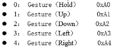
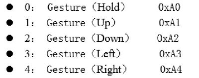
The address is stored with the result of gesture detection.
| address of gesture detection | |||
| 0: | Gesture(Hold) | 0xA0 | |
| 1: | Gesture(Up) | 0xA1 | |
| 2: | Gesture(Down) | 0xA2 | |
| 3: | Gesture(Left) | 0xA3 | |
| 4: | Gesture(Right) | 0xA4 | |
- 0x04: Proximity Date
This address holds the distance of the gesture from 0 to 255, the larger is near, the smaller is far.
How to Start
Use Uart
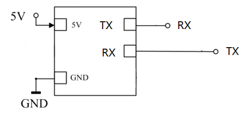
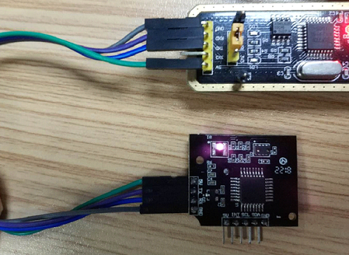
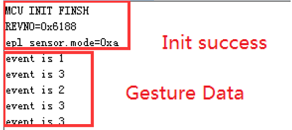
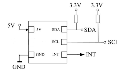
Connect product like the Circuit diagram , Set the Baud Rate as 115200
Using TTL-USB moudle, you can see the data like the picture
Use I2C
Connect product like the Circuit diagram
Set the SlaveAddress as 0x58,
Read Register 0x00, and result is 0xAA.
So, the I2C communicate success.
- Plan one : Polling
Every 100ms read once gesture data.
Read Register 0x03, and result is Gesture data.
- Plan two :Interrupt
Read once gesture data when trigger edge is falling edg.
Read Register 0x03, and result is Gesture data.
Need connect Pin INT.
