Difference between revisions of "BPI-CC2650 Zigbee BT Linaro 96Boars"
(→Harware spec) |
(→GPIO PIN define) |
||
| (20 intermediate revisions by the same user not shown) | |||
| Line 6: | Line 6: | ||
[[File:BPI-CC2650_Zigbee_BT_3.jpg|thumb|Overview]] | [[File:BPI-CC2650_Zigbee_BT_3.jpg|thumb|Overview]] | ||
| − | BPI-CC2650 Linaro 96Boars with TI CC2650 chip design developent board ,this is a Linaro 96Board standard development board. | + | BPI-CC2650 Linaro 96Boars with TI CC2650 chip design developent board ,this is a Linaro 96Board standard development board.The CC2650 device is a wireless MCU for Bluetooth Smart ZigBee and 6LoWPAN, as well as ZigBee RF4CE remote control applications |
1.BPI-CC2650 module: | 1.BPI-CC2650 module: | ||
| − | *TI CC2650 chip design with | + | *TI CC2650 chip design with Bluetooth4.2,ZigBee and 6LoWPAN |
| − | *TI | + | *TI CC2640 chip design with Bluetooth4.2 and Bluetooth 5 |
| + | *TI CC2630 6LoWPAN, ZigBee | ||
*Linaro 96Board standard | *Linaro 96Board standard | ||
=Hardware= | =Hardware= | ||
==Hardware inerface== | ==Hardware inerface== | ||
| + | [[File:BPI-CC2650_interface.jpg]] | ||
| + | ==Harware spec== | ||
| + | {| class="wikitable" | ||
| + | |- | ||
| + | | style="background: PaleTurquoise; color: black" colspan="4"| ''HardwareSpecification of BPi-CC2650'' | ||
| + | |- | ||
| + | | Soc || TI CC2650 (option:CC2640 CC2630) | ||
| + | |- | ||
| + | | CPU || ARM Cortex™-M3 CPU | ||
| + | |- | ||
| + | | SDRAM size || 20 KB of ultralow-Leakage SRAM, 8KB of SRAM for Cache | ||
| + | |- | ||
| + | | Flash size || 128KB | ||
| + | |- | ||
| + | | Power || 5V/2A via MicroUSB / 3.7V via Battery Connector | ||
| + | |- | ||
| + | | Low-level peripherals || 40 Pins Header \2xSSI,I2C,I2S,UART;All Digital Peripheral Pins Can Be Routed to Any GPIO | ||
| + | |- | ||
| + | | On board Network || Zigbee, BT4.2 | ||
| + | |- | ||
| + | | micro USB || 1 micro USB to Uart for debug | ||
| + | |- | ||
| + | | Buttons || Reset button, User button | ||
| + | |- | ||
| + | | Leds || 1 Power status Led and 4 other Leds | ||
| + | |- | ||
| + | | Sizes || 60mm×30mm | ||
| + | |- | ||
| + | | Weight || 10g | ||
| + | |- | ||
| + | |} | ||
| − | == | + | ==GPIO PIN define== |
| + | |||
| + | <div id="Banana Pi"></div> | ||
| + | {| border="0" cellpadding="10" width="100%" | ||
| + | |- | ||
| + | |width="12%" valign="top" align="left"| | ||
| + | |||
| + | {| class="wikitable" | ||
| + | |- | ||
| + | | style="background: PaleTurquoise; color: black" colspan="4"| ''BPI-CC2650 40PIN GPIO (CON2)'' | ||
| + | |- | ||
| + | |GPIO Pin Name || Default Function | ||
| + | |- | ||
| + | |CON2-P01|| GND | ||
| + | |- | ||
| + | |CON2-P02|| GND | ||
| + | |- | ||
| + | |CON2-P03|| DIO_29 | ||
| + | |- | ||
| + | |CON2-P04|| Power_EN | ||
| + | |- | ||
| + | |CON2-P05|| DIO_1 BLE_TX | ||
| + | |- | ||
| + | |CON2-P06|| nRESET | ||
| + | |- | ||
| + | |CON2-P07|| DIO_2 BLE_RX | ||
| + | |- | ||
| + | |CON2-P08|| DIO_28 | ||
| + | |- | ||
| + | |CON2-P09|| DIO_27 | ||
| + | |- | ||
| + | |CON2-P10|| DIO_26 | ||
| + | |- | ||
| + | |CON2-P11|| DIO_1 BLE_TX | ||
| + | |- | ||
| + | |CON2-P12|| DIO_25 | ||
| + | |- | ||
| + | |CON2-P13|| DIO_2 BLE_RX | ||
| + | |- | ||
| + | |CON2-P14|| DIO_24 | ||
| + | |- | ||
| + | |CON2-P15|| DIO_23 | ||
| + | |- | ||
| + | |CON2-P16|| DIO_22 | ||
| + | |- | ||
| + | |CON2-P17|| DIO_21 | ||
| + | |- | ||
| + | |CON2-P18|| DIO_20 | ||
| + | |- | ||
| + | |CON2-P19|| DIO_19 | ||
| + | |- | ||
| + | |CON2-P20|| DIO_18 | ||
| + | |- | ||
| + | |} | ||
| + | |||
| + | |width="12%" valign="top" align="left"| | ||
| + | {| class="wikitable" | ||
| + | |- | ||
| + | | style="background: PaleTurquoise; color: black" colspan="4"| ''BPI-CC2650 40PIN GPIO (CON2)'' | ||
| + | |- | ||
| + | |GPIO Pin Name || Default Function | ||
| + | |- | ||
| + | |CON2-P21|| DIO_15 | ||
| + | |- | ||
| + | |CON2-P22|| DIO_14 | ||
| + | |- | ||
| + | |CON2-P23|| DIO_13 | ||
| + | |- | ||
| + | |CON2-P24|| DIO_12 | ||
| + | |- | ||
| + | |CON2-P25|| DIO_11 | ||
| + | |- | ||
| + | |CON2-P26|| DIO_10 | ||
| + | |- | ||
| + | |CON2-P27|| DIO_9 | ||
| + | |- | ||
| + | |CON2-P28|| DIO_8 | ||
| + | |- | ||
| + | |CON2-P29|| DIO_7 | ||
| + | |- | ||
| + | |CON2-P30|| DIO_6 | ||
| + | |- | ||
| + | |CON2-P31|| DIO_5 | ||
| + | |- | ||
| + | |CON2-P32|| DIO_4 | ||
| + | |- | ||
| + | |CON2-P33|| DIO_3 | ||
| + | |- | ||
| + | |CON2-P34|| DIO_0 | ||
| + | |- | ||
| + | |CON2-P35|| VCC_1.8V | ||
| + | |- | ||
| + | |CON2-P36|| NC | ||
| + | |- | ||
| + | |CON2-P37|| VCC_5V | ||
| + | |- | ||
| + | |CON2-P38|| NC | ||
| + | |- | ||
| + | |CON2-P39|| GND | ||
| + | |- | ||
| + | |CON2-P40|| GND | ||
| + | |- | ||
| + | |} | ||
| + | |width="12%" valign="top" align="left"| | ||
| + | {| class="wikitable" | ||
| + | |- | ||
| + | | style="background: PaleTurquoise; color: black" colspan="4"| ''BPI-CC2650 UART(CON1)'' | ||
| + | |- | ||
| + | |CON1-P1|| GND | ||
| + | |- | ||
| + | |CON1-P2|| BLE_RX | ||
| + | |- | ||
| + | |CON1-P3|| BLE_TX | ||
| + | |- | ||
| + | |} | ||
| + | |width="12%" valign="top" align="left"| | ||
| + | {| class="wikitable" | ||
| + | |- | ||
| + | | style="background: PaleTurquoise; color: black" colspan="4"| ''BPI-CC2650 TI JTAG(CON3)'' | ||
| + | |- | ||
| + | |CSI Pin Name || Default Function | ||
| + | |- | ||
| + | |CN3-P1 || JTAG_TCK | ||
| + | |- | ||
| + | |CN3-P2 ||GND | ||
| + | |- | ||
| + | |CN3-P3 ||JTAG TDO | ||
| + | |- | ||
| + | |CN3-P4 ||VDDS | ||
| + | |- | ||
| + | |CN3-P5 ||JTAG_TMS | ||
| + | |- | ||
| + | |CN3-P6 ||nRESET | ||
| + | |- | ||
| + | |CN3-P7 ||NC | ||
| + | |- | ||
| + | |CN3-P8 ||NC | ||
| + | |- | ||
| + | |CN3-P9 ||JTAG TDI | ||
| + | |- | ||
| + | |CN3-P10|| GND | ||
| + | |- | ||
| + | |} | ||
| + | |width="12%" valign="top" align="left"| | ||
| + | |width="12%" valign="top" align="left"| | ||
| + | |} | ||
=Resources= | =Resources= | ||
==Source code== | ==Source code== | ||
| + | *TI source code download : http://www.ti.com/product/CC2650/toolssoftware | ||
==Documents== | ==Documents== | ||
| + | *TI CC2650 official website: http://www.ti.com/product/CC2650?keyMatch=CC2650&tisearch=Search-EN-Everything | ||
| + | *TI CC2650 datasheet: https://drive.google.com/file/d/1-RSfXwizV6Iwwb-U1EYFWrfGiPMA4ynl/view?usp=sharing | ||
| + | *TI CC2630 datasheet: https://drive.google.com/file/d/1aCdC7vZ23vWKjidY69ZgiNrYTTMbSBt1/view?usp=sharing | ||
Latest revision as of 23:38, 5 June 2018
BPI NB-IoT Linaro 96Boars with Quecte BC95 module developent board
Contents
Introduction
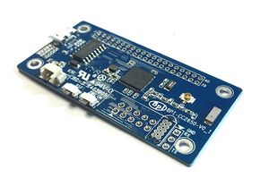
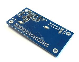
BPI-CC2650 Linaro 96Boars with TI CC2650 chip design developent board ,this is a Linaro 96Board standard development board.The CC2650 device is a wireless MCU for Bluetooth Smart ZigBee and 6LoWPAN, as well as ZigBee RF4CE remote control applications
1.BPI-CC2650 module:
- TI CC2650 chip design with Bluetooth4.2,ZigBee and 6LoWPAN
- TI CC2640 chip design with Bluetooth4.2 and Bluetooth 5
- TI CC2630 6LoWPAN, ZigBee
- Linaro 96Board standard
Hardware
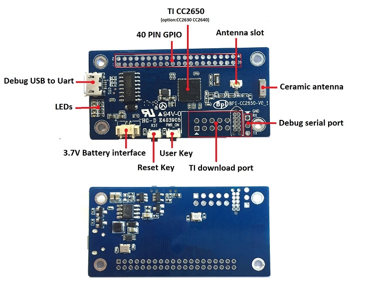
Hardware inerface
Harware spec
| HardwareSpecification of BPi-CC2650 | |||
| Soc | TI CC2650 (option:CC2640 CC2630) | ||
| CPU | ARM Cortex™-M3 CPU | ||
| SDRAM size | 20 KB of ultralow-Leakage SRAM, 8KB of SRAM for Cache | ||
| Flash size | 128KB | ||
| Power | 5V/2A via MicroUSB / 3.7V via Battery Connector | ||
| Low-level peripherals | 40 Pins Header \2xSSI,I2C,I2S,UART;All Digital Peripheral Pins Can Be Routed to Any GPIO | ||
| On board Network | Zigbee, BT4.2 | ||
| micro USB | 1 micro USB to Uart for debug | ||
| Buttons | Reset button, User button | ||
| Leds | 1 Power status Led and 4 other Leds | ||
| Sizes | 60mm×30mm | ||
| Weight | 10g | ||
GPIO PIN define
|
|
|
|
||||||||||||||||||||||||||||||||||||||||||||||||||||||||||||||||||||||||||||||||||||||||||||||||||||||||||||||||||||||||||||||||||
Resources
Source code
- TI source code download : http://www.ti.com/product/CC2650/toolssoftware
Documents
- TI CC2650 official website: http://www.ti.com/product/CC2650?keyMatch=CC2650&tisearch=Search-EN-Everything
- TI CC2650 datasheet: https://drive.google.com/file/d/1-RSfXwizV6Iwwb-U1EYFWrfGiPMA4ynl/view?usp=sharing
- TI CC2630 datasheet: https://drive.google.com/file/d/1aCdC7vZ23vWKjidY69ZgiNrYTTMbSBt1/view?usp=sharing


