Difference between revisions of "BPI-PicoW-S3"
(→Espressif ESP32-S3) |
|||
| (29 intermediate revisions by 4 users not shown) | |||
| Line 5: | Line 5: | ||
[[File:PICO-1000-7.jpg|thumb|[[BPI-PicoW-S3 ]]with ESP32-S3]] | [[File:PICO-1000-7.jpg|thumb|[[BPI-PicoW-S3 ]]with ESP32-S3]] | ||
| − | [[File: | + | [[File:Banana_Pi_BPI-PicoW-S3_5.jpg|thumb|[[BPI-PicoW-S3 ]]with ESP32-S3]] |
| + | [[File:BPI-Centi-S3_2.jpg|thumb|[[BPI-Centi-S3]] with ESP32-S3 front]] | ||
[[File:Leaf-S3-incline-front.jpg|thumb|[[BPI-Leaf-S3]] with ESP32-S3]] | [[File:Leaf-S3-incline-front.jpg|thumb|[[BPI-Leaf-S3]] with ESP32-S3]] | ||
[[File:Smart-01-03.gif|thumb|[[BPI-Smart ]]with ESP8266]] | [[File:Smart-01-03.gif|thumb|[[BPI-Smart ]]with ESP8266]] | ||
| Line 17: | Line 18: | ||
*ESP32-S3, Xtensa® 32 bit LX7 | *ESP32-S3, Xtensa® 32 bit LX7 | ||
| − | * | + | * In-packge PSRAM 2MB, Extereal FLASH 8MB |
* Ultra-low power 10uA | * Ultra-low power 10uA | ||
* 2.4G WIFI, Bluetooth 5, Bluetooth mesh | * 2.4G WIFI, Bluetooth 5, Bluetooth mesh | ||
* GPIO, ADC, TOUCH, PWM, I2C, SPI, RMT, I2S, UART, LCD, CAMERA, USB, JTAG | * GPIO, ADC, TOUCH, PWM, I2C, SPI, RMT, I2S, UART, LCD, CAMERA, USB, JTAG | ||
*1*microUSB | *1*microUSB | ||
| − | *1* | + | *1*Neopixel LED |
| − | == BPI-PicoW-S3 VS | + | == BPI-PicoW-S3 VS Raspberry Pi PicoW, BPI-Leaf-S3, ESP32-S3-DevKitC-1 == |
{| class="wikitable" | {| class="wikitable" | ||
| Line 30: | Line 31: | ||
! Development board | ! Development board | ||
!BPI-PicoW-S3 | !BPI-PicoW-S3 | ||
| − | ! | + | !Raspberry Pi PicoW |
!BPI-Leaf-S3 | !BPI-Leaf-S3 | ||
!ESP32-S3-DevKitC-1 | !ESP32-S3-DevKitC-1 | ||
| Line 108: | Line 109: | ||
* Security mechanism: ESP32-S3 provides comprehensive security mechanism and protection measures for iot devices to prevent all kinds of malicious attacks and threats. It supports Flash encryption based on AES-XTS algorithm, secure startup based on RSA algorithm, digital signature and HMAC. Esp32-s3 also includes a new "World Controller" module, which provides two non-interfering execution environments to implement a trusted execution environment or permission separation mechanism. | * Security mechanism: ESP32-S3 provides comprehensive security mechanism and protection measures for iot devices to prevent all kinds of malicious attacks and threats. It supports Flash encryption based on AES-XTS algorithm, secure startup based on RSA algorithm, digital signature and HMAC. Esp32-s3 also includes a new "World Controller" module, which provides two non-interfering execution environments to implement a trusted execution environment or permission separation mechanism. | ||
| + | |||
| + | ==Getting Start== | ||
| + | |||
| + | *[https://bpi-steam.com/PicoW_S3_doc/en/ Getting Started with BPI-PicoW-S3] | ||
= Hardware = | = Hardware = | ||
| Line 134: | Line 139: | ||
|- | |- | ||
| On-chip SRAM | | On-chip SRAM | ||
| − | | | + | | 512KB |
| + | |- | ||
| + | | Extereal FLASH | ||
| + | | 8MB | ||
|- | |- | ||
| − | | | + | | In-packge PSRAM |
| 2MB | | 2MB | ||
| − | |||
| − | |||
| − | |||
|- | |- | ||
| WIFI | | WIFI | ||
| Line 227: | Line 232: | ||
|- | |- | ||
| Controllable full color LED | | Controllable full color LED | ||
| + | | 1 | ||
| + | |- | ||
| + | | Controllable monochrome LED | ||
| 1 | | 1 | ||
|} | |} | ||
| − | == Size == | + | == Hardware Size == |
[[File:BPI-Pico-S3-board-dimension.png|800px]] | [[File:BPI-Pico-S3-board-dimension.png|800px]] | ||
| Line 415: | Line 423: | ||
| colspan="2" | Any GPIO | | colspan="2" | Any GPIO | ||
|- | |- | ||
| − | | Color LED | + | | Full Color LED |
| colspan="2" | GPIO 48 | | colspan="2" | GPIO 48 | ||
| + | |- | ||
| + | | Monochrome LED | ||
| + | | colspan="2" | GPIO 46 | ||
|} | |} | ||
= Software = | = Software = | ||
| + | |||
| + | == CircuitPython == | ||
| + | |||
| + | [[File:CircuitPython_Repo_header_logo.jpg | 800px]] | ||
| + | |||
| + | CircuitPython is an education-friendly open source derivative of MicroPython, supported and developed by Adafruit Industries. | ||
| + | |||
| + | In terms of ease of use, it goes a step further on the basis of MicroPython. | ||
| + | |||
| + | When the development board using CircuitPython firmware is connected to the PC, the PC will immediately get a USB storage disk. | ||
| + | |||
| + | And the python script file can be copied to this disk to allow the program to run on the development board. | ||
| + | |||
| + | This allows users to use it out of the box, because most modern personal operating systems and home PCs support USB storage disks. | ||
| + | |||
| + | Of course, in order to use REPL, at least a serial communication software needs to be installed, or a text editor that supports this function, such as Mu editor. | ||
| + | |||
| + | The CircuitPython community provides an extremely rich peripheral driver library, APIs documentation, and tutorials. | ||
| + | |||
| + | Even if there is no programming foundation, no hardware foundation, you can quickly get started from scratch. | ||
| + | |||
| + | CircuitPython does not support some microcontroller-specific libraries such as timer and hardware interrupt, nor does it support the multi-threaded _thread library. It only provides the asyncio library for writing concurrent code. | ||
| + | |||
| + | The code is very portable between microcontrollers supported by CircuitPython and single-board computers (SBCs) supported by Blinka. This is thanks to its efforts to unify APIs. | ||
| + | |||
| + | * [https://codewith.mu/ Mu Editor Download Page] | ||
| + | |||
| + | * [[ code_circuitpython_with_mu_en | Getting Started: Code CircuitPython with Mu Editor ]] | ||
| + | |||
| + | '''Supported by the adafruit/circuitpython GitHub repository''' | ||
| + | |||
| + | https://github.com/adafruit/circuitpython/pull/7031 | ||
| + | |||
| + | '''Supported by the adafruit/tinyuf2 GitHub repository''' | ||
| + | |||
| + | https://github.com/adafruit/tinyuf2/pull/250 | ||
| + | |||
| + | '''Reference Resources''' : | ||
| + | |||
| + | * [https://learn.adafruit.com/welcome-to-circuitpython Adafruit: Welcome To CircuitPython] | ||
| + | |||
| + | * [https://learn.adafruit.com/getting-started-with-web-workflow-using-the-code-editor/overview Adafruit:CircuitPython Web Workflow Code Editor Quick Start] | ||
| + | |||
| + | * [https://circuitpython.readthedocs.io/ Adafruit:CircuitPython Docs] | ||
| + | |||
| + | * [https://github.com/todbot/circuitpython-tricks GitHub:CircuitPython-tricks] | ||
| + | |||
| + | * [https://forum.banana-pi.org/t/bpi-pico-s3-getting-started-code-circuitpython-with-mu-editor/13969 BPI-Pico-S3 Getting Started, Code CircuitPython with Mu Editor] | ||
==ESP-IDF== | ==ESP-IDF== | ||
| Line 456: | Line 515: | ||
[[File:Mircopython.png | 800px]] | [[File:Mircopython.png | 800px]] | ||
| − | MicroPython | + | MicroPython is a lean and efficient implementation of the Python 3 programming language that includes a small subset of the Python standard library and is optimised to run on microcontrollers and in constrained environments. |
| + | |||
| + | Crowdfunded and open sourced in 2013 by Damien P. George. | ||
| + | |||
| + | The most obvious difference between it and the use of C programs to develop microcontrollers is that there is no need for lengthy compilation when verifying code. | ||
| + | |||
| + | Using serial communication software, enter commands through the REPL(read-eval-print-loop) to control the microcontroller, just like Python's REPL. | ||
| + | |||
| + | It is also possible to use some tools to upload a python script file to run inside the microcontroller. | ||
| + | |||
| + | Its implementation of Python3 includes the _thread library that supports multithreading and the asyncio library for writing concurrent code. | ||
| − | + | MicroPython aims to be as compatible with normal Python as possible to allow you to transfer code with ease from the desktop to a microcontroller or embedded system. | |
| − | + | At the same time it also has some libraries specific for microcontrollers in order to take full advantage of the hardware features inside the microcontroller chip, such as timers, hardware interrupts, WiFi, etc., depending on the specific hardware. | |
| − | + | While having the above features, it is compact enough to fit and run within just 256k of code space and 16k of RAM. | |
| − | + | If you know Python you already know MicroPython. | |
| + | |||
| + | On the other hand, the more you learn about MicroPython the better you become at Python. | ||
==Arduino== | ==Arduino== | ||
| Line 470: | Line 541: | ||
[[File:Arduino_logo_1200x350.png | 800px]] | [[File:Arduino_logo_1200x350.png | 800px]] | ||
| − | Arduino is an open source embedded software | + | Arduino is an open source embedded hardware and software development platform for users to create interactive embedded projects. |
| + | |||
| + | The Arduino integrated development environment (IDE) is the software core of this platform, using the C/C++ programming language to develop projects. | ||
| + | |||
| + | The biggest feature of Arduino is to provide a unified API to develop all microcontrollers it supports, with very good code portability and reusability. | ||
| + | |||
| + | In addition, it simplifies the process of building a development environment, and all the development environments of microcontrollers it supports can be installed and configured with one click. | ||
| + | |||
| + | It also provides simple one-click mechanisms to compile and upload programs to a microcontroller. | ||
| + | |||
| + | Arduino IDE also integrates many routines, supplemented by a large number of comments, which can help users get started quickly. | ||
| + | |||
| + | A large number of excellent open source projects accumulated in the Arduino community are available for reference and learning, and there are quite a few driver libraries and APIs provided by chip manufacturers. | ||
* [https://www.arduino.cc/en/software Arduino IDE download address] | [https://docs.espressif.com/projects/arduino-esp32/en/latest/installing.html#installing Install and configure Arduino-ESP32 operating environment] | * [https://www.arduino.cc/en/software Arduino IDE download address] | [https://docs.espressif.com/projects/arduino-esp32/en/latest/installing.html#installing Install and configure Arduino-ESP32 operating environment] | ||
| Line 477: | Line 560: | ||
=Resources= | =Resources= | ||
| + | BPI-PicoW-S3 schematic : https://github.com/BPI-STEAM/BPI-PicoW-Doc/blob/main/sch/BPI-PicoW-V0.4.pdf | ||
=Easy to buy sample= | =Easy to buy sample= | ||
| − | * Official AliExpress: | + | * Official AliExpress:https://www.aliexpress.com/item/1005004775634442.html |
| − | * Official Taobao: | + | * SinoVoip Aliexpress : https://www.aliexpress.com/item/1005004775859077.html |
| + | * Official Taobao: https://item.taobao.com/item.htm?spm=a2126o.success.0.0.25b04831CHV1Nc&id=684134360199 | ||
* OEM&OEM customized service: [email protected] | * OEM&OEM customized service: [email protected] | ||
Latest revision as of 17:28, 10 September 2023
Introduction
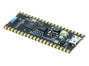
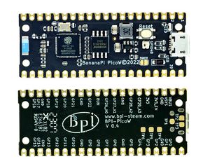
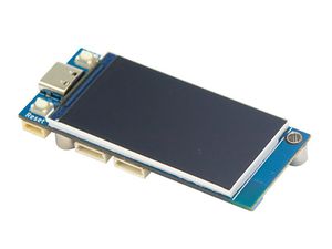
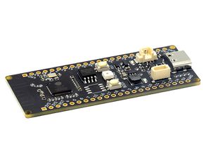
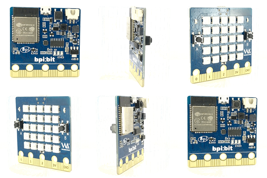
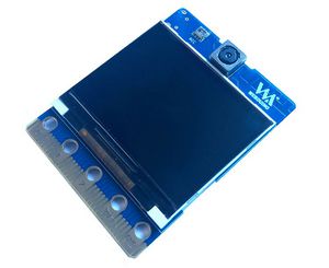
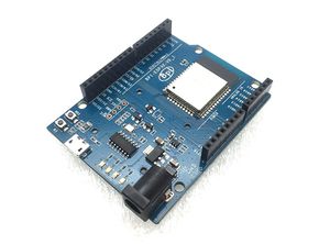
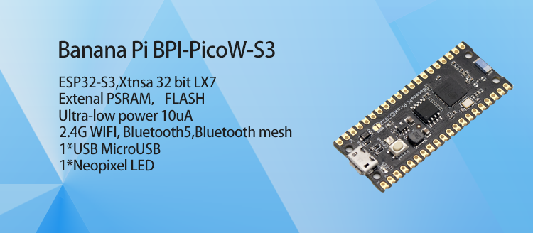
The Banana Pi BPI-PicoW-S3 is a series of low-powered microcontrollers designed for IoT development and Maker DIY board.same size as Raspberry Pi Pico board,It supports 2.4 GHz Wi-Fi and Bluetooth® LE dual-mode wireless communication, the peripheral is compatible with low-power hardware design, and the power consumption is only 10uA in deep sleep mode.In terms of programming, the PicoW-S3 supports ESP-IDF, Arduino, micropython and other methods.
key features
- ESP32-S3, Xtensa® 32 bit LX7
- In-packge PSRAM 2MB, Extereal FLASH 8MB
- Ultra-low power 10uA
- 2.4G WIFI, Bluetooth 5, Bluetooth mesh
- GPIO, ADC, TOUCH, PWM, I2C, SPI, RMT, I2S, UART, LCD, CAMERA, USB, JTAG
- 1*microUSB
- 1*Neopixel LED
BPI-PicoW-S3 VS Raspberry Pi PicoW, BPI-Leaf-S3, ESP32-S3-DevKitC-1
| Development board | BPI-PicoW-S3 | Raspberry Pi PicoW | BPI-Leaf-S3 | ESP32-S3-DevKitC-1 |
|---|---|---|---|---|
| GPIO pinout | 27 | 27 | 36 | 36 |
| 3.3v pin | 1 | 1 | 2 | 2 |
| 5v pin | 2 | 2 | 1 | 1 |
| GND pin | 8 | 8 | 4 | 4 |
| Full color LED | 1 on GPIO48 | None | 1 on GPIO48 | 1 on GPIO48 |
| Chip directly connected to USB | MicroUSB port x1 | MicroUSB port x1 | Type-C USB port x1 | MicroUSB port x1 |
| UART TTL to USB | None | None | None | CP2102-MicroUSB interface x1 |
| External battery socket | None | None | 3.7v lithium battery power supply interface | None |
| Battery charging | None | None | 500mA charging | None |
| I²C 4pin connector | None | None | 1 | None |
Espressif ESP32-S3
Esp32-S3 is an MCU chip that integrates 2.4 GHz Wi-Fi and Bluetooth 5 (LE) and supports Long Range mode. The ESP32-S3 runs on an Xtensa® 32-bit LX7 dual-core processor with a high frequency of 240 MHz, 512 KB built-in SRAM (TCM), 45 programmable GPIO pins, and a rich communication interface. Esp32-s3 supports larger capacity of high-speed Octal SPI flash and off-chip RAM, and supports user-configured data caching and instruction caching.
What follows is a description of the most important features of ESP32-S3.
- Wi-Fi + Bluetooth 5 (LE) Wireless Connectivity: ESP32-S3 supports a 2.4 GHz Wi-Fi (802.11 b/g/n) with 40 MHz of bandwidth support. The Bluetooth Low Energy subsystem supports long range through Coded PHY and advertisement extension. It also supports higher transmission speed and data throughput, with 2 Mbps PHY. Both Wi-Fi and BLE have superior RF performance that is maintained even at high temperatures.
- AI Acceleration Support: ESP32-S3 has additional support for vector instructions in the MCU, which provides acceleration for neural network computing and signal processing workloads. The software libraries for the above-mentioned optimized functions will become available very soon, in the form of updates to ESP-DSP and ESP-NN.
- Rich IO interfaces: ESP32-S3 has 45 programmable GPIOs and common peripheral interfaces such as SPI, I2S, I2C, PWM, RMT, ADC, UART, SD/MMC host controller and TWAITM controller. Fourteen of the GPIOs can be configured as capacitive touch inputs for HMI interaction. In addition, ESP32-S3 is equipped with an ultra-low power coprocessor (ULP) and supports multiple low-power modes, making it widely applicable to various low-power application scenarios.
- Security mechanism: ESP32-S3 provides comprehensive security mechanism and protection measures for iot devices to prevent all kinds of malicious attacks and threats. It supports Flash encryption based on AES-XTS algorithm, secure startup based on RSA algorithm, digital signature and HMAC. Esp32-s3 also includes a new "World Controller" module, which provides two non-interfering execution environments to implement a trusted execution environment or permission separation mechanism.
Getting Start
Hardware
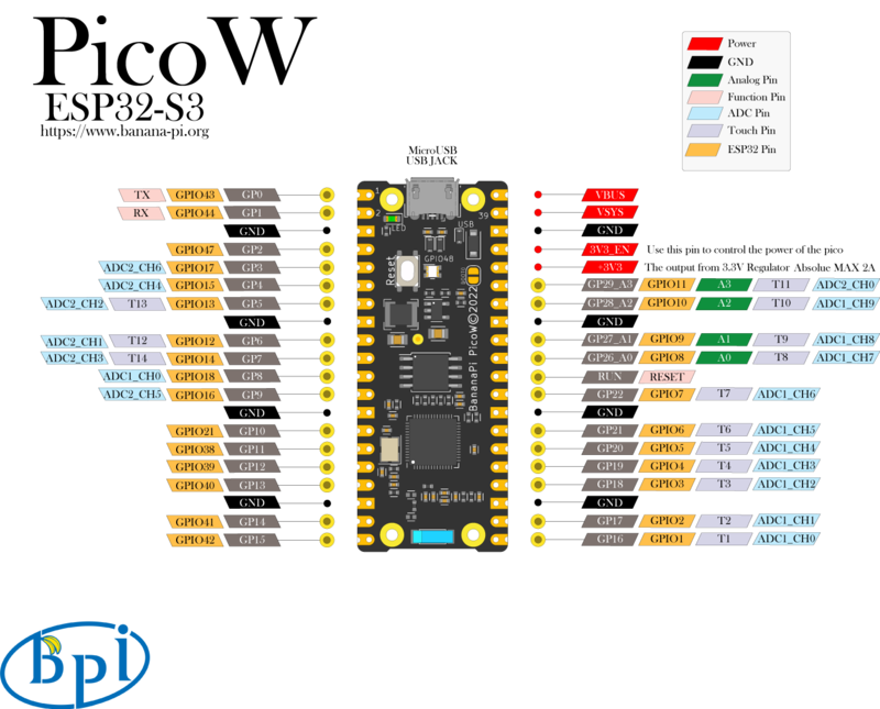
Hardware interface
Hardware spec
| BPI-PicoW-S3 Spec Sheet | |
|---|---|
| SoC | ESP32-S3, Xtensa® 32-bit LX7 dual core |
| Basic frequency | 240MHz MAX |
| Operating temperature | -40℃~+85℃ |
| On-chip ROM | 384KB |
| On-chip SRAM | 512KB |
| Extereal FLASH | 8MB |
| In-packge PSRAM | 2MB |
| WIFI | IEEE 802.11 b/g/n, 2.4Ghz band, 150Mbps |
| Bluetooth | Bluetooth 5, Bluetooth mesh |
| GPIO | BPI-PicoW-S3 has led out 27 available GPIOs |
| ADC | 2 × 12-bit SAR ADC supporting 18 analog channel inputs |
| TOUCH Capacitive Touch Sensor | 14 |
| SPI | 4 |
| I2C | 2. Support master or slave mode |
| I2S | 2, input and output of serial stereo data |
| LCD | 1, support 8-bit ~16-bit parallel RGB, I8080, MOTO6800 interface |
| CAMERA | 1, supports 8-bit ~16-bit DVP image sensor interface |
| UART | 3, supports asynchronous communication (RS232 and RS485) and IrDA |
| PWM | 8 independent channels, 14-bit precision |
| MCPWM | 2 |
| USB | 1 × Full Speed USB 2.0 OTG, MicroUSB Female |
| USB Serial/JTAG Controller | 1, USB full speed standard, CDC-ACM, JTAG |
| Temperature sensor | 1, the measurement range is –20 °C to 110 °C, for monitoring the internal temperature of the chip |
| SD/MMC | 1 × SDIO host interface, with 2 card slots, supports SD card 3.0 and 3.01, SDIO 3.0, CE-ATA 1.1, MMC 4.41, eMMC 4.5 and 4.51 |
| TWAI® Controller | 1, compatible with ISO11898-1 (CAN specification 2.0) |
| Generic DMA Controller | 5 receive channels and 5 transmit channels |
| RMT | 4-channel transmit, 4-channel receive, shared 384 x 32-bit RAM |
| Pulse Counter | 4 pulse count controllers (units), each unit has 2 independent channels |
| Timer | 4 × 54-bit general-purpose timers, 16-bit clock prescaler, 1 × 52-bit system timer, 3 × watchdog timers |
| External crystal | 40Mhz |
| RTC and Low Power Management | Power Management Unit (PMU) + Ultra Low Power Coprocessor (ULP) |
| Low power consumption current | 10uA |
| Working Voltage | 3.3V |
| Input voltage | 3.3V~5.5V |
| Maximum discharge current | [email protected] DC/DC |
| Controllable full color LED | 1 |
| Controllable monochrome LED | 1 |
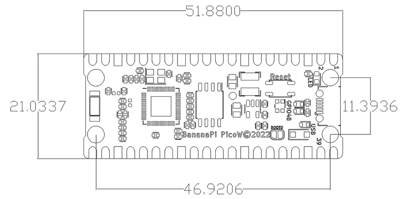
Hardware Size
| BPI-PicoW-S3 size chart | |
|---|---|
| Pin spacing | 2.54mm |
| Hole Spacing | 11.4mm/ 47mm |
| Hole size | Inner diameter 2.1mm/Outer diameter 3.4mm |
| Mainboard size | 21 × 51.88(mm)/0.83 x 2.04(inches) |
| Thickness | 1.2mm |
The pin spacing is compatible with universal boards (hole boards, dot matrix boards) and breadboards, which is convenient for debugging applications.
GPIO define
| BPI-PicoW-S3 peripheral GPIO pin assignment | ||
|---|---|---|
| Peripheral Interface | Signal | Pins |
| ADC | ADC1_CH0~9 | GPIO 1~10 |
| ADC2_CH0~9 | GPIO 11~20 | |
| Touch Sensor | TOUCH1~14 | GPIO 1~14 |
| JTAG | MTCK | GPIO 39 |
| MTDO | GPIO 40 | |
| MTDI | GPIO 41 | |
| MTMS | GPIO 42 | |
| UART | Default assigned pins, can be redefined as any GPIO | |
| U0RXD_in | GPIO 44 | |
| U0CTS_in | GPIO 16 | |
| U0DSR_in | Any GPIO | |
| U0TXD_out | GPIO43 | |
| U0RTS_out | GPIO 15 | |
| U0DTR_out | Any GPIO | |
| U1RXD_in | GPIO 18 | |
| U1CTS_in | GPIO 20 | |
| U1DSR_in | Any GPIO | |
| U1TXD_out | GPIO 17 | |
| U1RTS_out | GPIO 19 | |
| U1DTR_out | Any GPIO | |
| U2 | Any GPIO | |
| I2C | Any GPIO | |
| PWM | Any GPIO | |
| I2S | Any GPIO | |
| LCD | Any GPIO | |
| CAMERA | Any GPIO | |
| RMT | Any GPIO | |
| SPI0/1 | Used for FLASH and PSRAM | |
| SPI2/3 | Any GPIO | |
| Pulse Counter | Any GPIO | |
| USB OTG | D- | GPIO 19 (internal PHY) |
| D+ | GPIO 20 (internal PHY) | |
| VP | GPIO 42 (External PHY) | |
| VM | GPIO 41 (External PHY) | |
| RCV | GPIO21 (External PHY) | |
| OEN | GPIO 40 (External PHY) | |
| VPO | GPIO 39 (External PHY) | |
| VMO | GPIO38 (External PHY) | |
| USB Serial/JTAG | D- | GPIO 19 (internal PHY) |
| D+ | GPIO 20 (internal PHY) | |
| VP | GPIO 42 (External PHY) | |
| VM | GPIO 41 (External PHY) | |
| OEN | GPIO 40 (External PHY) | |
| VPO | GPIO 39 (External PHY) | |
| VMO | GPIO38 (External PHY) | |
| SD/MMC | Any GPIO | |
| MCPWM | Any GPIO | |
| TWAI | Any GPIO | |
| Full Color LED | GPIO 48 | |
| Monochrome LED | GPIO 46 | |
Software
CircuitPython
CircuitPython is an education-friendly open source derivative of MicroPython, supported and developed by Adafruit Industries.
In terms of ease of use, it goes a step further on the basis of MicroPython.
When the development board using CircuitPython firmware is connected to the PC, the PC will immediately get a USB storage disk.
And the python script file can be copied to this disk to allow the program to run on the development board.
This allows users to use it out of the box, because most modern personal operating systems and home PCs support USB storage disks.
Of course, in order to use REPL, at least a serial communication software needs to be installed, or a text editor that supports this function, such as Mu editor.
The CircuitPython community provides an extremely rich peripheral driver library, APIs documentation, and tutorials.
Even if there is no programming foundation, no hardware foundation, you can quickly get started from scratch.
CircuitPython does not support some microcontroller-specific libraries such as timer and hardware interrupt, nor does it support the multi-threaded _thread library. It only provides the asyncio library for writing concurrent code.
The code is very portable between microcontrollers supported by CircuitPython and single-board computers (SBCs) supported by Blinka. This is thanks to its efforts to unify APIs.
Supported by the adafruit/circuitpython GitHub repository
https://github.com/adafruit/circuitpython/pull/7031
Supported by the adafruit/tinyuf2 GitHub repository
https://github.com/adafruit/tinyuf2/pull/250
Reference Resources :
ESP-IDF
ESP-IDF is an IoT development framework officially launched by Espressif, supporting Windows, Linux and macOS operating systems.
It is recommended that developers install ESP-IDF via an integrated development environment (IDE):
- GitHub: ESP-IDF Eclipse Plugin Installation and Usage Guide
- ESP-IDF VSCode plugin | /master/docs/tutorial/toc.md GitHub: Installation and Usage Guide | bilibili: ESP-IDF VSCode Plugin Quick Operation Guide
Or select the corresponding manual installation process according to the operating system:
- Standard setup for Windows platform toolchain
- Standard setup for Linux and macOS platform toolchains
API:
In order to enable your BPI-Leaf-S3 development board to flash FLASH through USB-CDC, you need to set the development board to firmware download mode.
There are two methods of operation:
1. Connect to the computer via USB, press and hold the BOOT button, then press the RESET button and release it, and finally release the BOOT button.
2. Press and hold the BOOT button when the power supply is disconnected, then connect to the computer via USB, and finally release the BOOT button.
You need to confirm the interface in the device manager. The serial number of the interface in the firmware download mode and the normal mode may be different.
MicroPython
MicroPython is a lean and efficient implementation of the Python 3 programming language that includes a small subset of the Python standard library and is optimised to run on microcontrollers and in constrained environments.
Crowdfunded and open sourced in 2013 by Damien P. George.
The most obvious difference between it and the use of C programs to develop microcontrollers is that there is no need for lengthy compilation when verifying code.
Using serial communication software, enter commands through the REPL(read-eval-print-loop) to control the microcontroller, just like Python's REPL.
It is also possible to use some tools to upload a python script file to run inside the microcontroller.
Its implementation of Python3 includes the _thread library that supports multithreading and the asyncio library for writing concurrent code.
MicroPython aims to be as compatible with normal Python as possible to allow you to transfer code with ease from the desktop to a microcontroller or embedded system.
At the same time it also has some libraries specific for microcontrollers in order to take full advantage of the hardware features inside the microcontroller chip, such as timers, hardware interrupts, WiFi, etc., depending on the specific hardware.
While having the above features, it is compact enough to fit and run within just 256k of code space and 16k of RAM.
If you know Python you already know MicroPython.
On the other hand, the more you learn about MicroPython the better you become at Python.
Arduino
Arduino is an open source embedded hardware and software development platform for users to create interactive embedded projects.
The Arduino integrated development environment (IDE) is the software core of this platform, using the C/C++ programming language to develop projects.
The biggest feature of Arduino is to provide a unified API to develop all microcontrollers it supports, with very good code portability and reusability.
In addition, it simplifies the process of building a development environment, and all the development environments of microcontrollers it supports can be installed and configured with one click.
It also provides simple one-click mechanisms to compile and upload programs to a microcontroller.
Arduino IDE also integrates many routines, supplemented by a large number of comments, which can help users get started quickly.
A large number of excellent open source projects accumulated in the Arduino community are available for reference and learning, and there are quite a few driver libraries and APIs provided by chip manufacturers.
- Arduino IDE download address | Install and configure Arduino-ESP32 operating environment
- GitHub: BPI-Leaf-S3 Arduino Quick Start
- Arduino-ESP32 APIs
Resources
BPI-PicoW-S3 schematic : https://github.com/BPI-STEAM/BPI-PicoW-Doc/blob/main/sch/BPI-PicoW-V0.4.pdf
Easy to buy sample
- Official AliExpress:https://www.aliexpress.com/item/1005004775634442.html
- SinoVoip Aliexpress : https://www.aliexpress.com/item/1005004775859077.html
- Official Taobao: https://item.taobao.com/item.htm?spm=a2126o.success.0.0.25b04831CHV1Nc&id=684134360199
- OEM&OEM customized service: [email protected]
