Difference between revisions of "BPI-Bit-S2"
(→Hardware upgrade and function comparison) |
|||
| (53 intermediate revisions by 2 users not shown) | |||
| Line 1: | Line 1: | ||
| − | [[zh:BPI-Bit | + | [[zh:BPI-Bit-S2 STEAM 教育开发板]] |
| − | =About BPI | + | =About BPI-Bit-S2 = |
| − | [[File:Bpi_bit_v2_1.jpg|thumb|[[BPI-Bit | + | [[File:Bpi_bit_v2_1.jpg|thumb|[[BPI-Bit-S2]] with ESP32-S2]] |
[[File:Webduino_gif.gif|thumb|[[BPI-Bit]] with ESP32]] | [[File:Webduino_gif.gif|thumb|[[BPI-Bit]] with ESP32]] | ||
[[File:Leaf-S3-incline-front.jpg|thumb|[[BPI-Leaf-S3]] with ESP32-S3]] | [[File:Leaf-S3-incline-front.jpg|thumb|[[BPI-Leaf-S3]] with ESP32-S3]] | ||
| + | [[File:BPI-Centi-S3_2.jpg|thumb|[[BPI-Centi-S3]] with ESP32-S3 front]] | ||
[[File:BPI-AI_1.JPG|thumb|[[BPI-AI]] Kendryte K210 RISC-V]] | [[File:BPI-AI_1.JPG|thumb|[[BPI-AI]] Kendryte K210 RISC-V]] | ||
[[File:ESP32_6.JPG|thumb|[[BPI-UNO32]] with ESP32 design]] | [[File:ESP32_6.JPG|thumb|[[BPI-UNO32]] with ESP32 design]] | ||
| − | [[File:BPI- | + | [[File:BPI-Bit-S2_banner.jpg|800px]] |
| − | '''BPI | + | '''BPI-Bit-S2''' development board is a successor to [[BPI-Bit]], inheriting most of the hardware functions. |
| − | + | IO is compatible with micro:bit and can use most peripheral accessories of micro:bit. | |
| − | == | + | Support Webduino, Arduino, MicroPython & CircuitPython programming environment suitable for STEAM education. |
| + | |||
| + | == Key features == | ||
* ESP32-S2 | * ESP32-S2 | ||
* 5x5 RGB LED matrix | * 5x5 RGB LED matrix | ||
* 1 buzzer | * 1 buzzer | ||
| − | * 1 | + | * 1 thermistor sensor |
* 2 photosensitive sensors | * 2 photosensitive sensors | ||
| − | * 2 | + | * 2 programmable keys,1 BOOT key,1 Reset key |
* Type-C USB interface | * Type-C USB interface | ||
* Size 5x5cm | * Size 5x5cm | ||
* The Goldfinger Edge Connector definition is fully compatible with Micro: Bit | * The Goldfinger Edge Connector definition is fully compatible with Micro: Bit | ||
| − | == | + | == Feature comparison == |
| − | {| class="wikitable" | + | {| class="wikitable" style="width: 50%;" |
|- | |- | ||
| − | ! colspan="3" style="text-align:center; background-color:#FFCB2F;" | | + | ! colspan="3" style="text-align:center; background-color:#FFCB2F;" | micro:bit vs BPI-Bit-S2 |
|- | |- | ||
| − | | | + | | Product |
| − | | | + | | micro:bit V2.2X |
| − | | BPI | + | | BPI-Bit-S2 |
|- | |- | ||
| − | | | + | | MCU |
| − | | | + | | Nordic nRF52833 |
| − | | ESP32-S2 | + | | Espressif ESP32-S2 |
|- | |- | ||
| − | | | + | | Frequency |
| − | | | + | | 64MHz |
| − | | | + | | 240MHz |
|- | |- | ||
| RAM | | RAM | ||
| − | | | + | | 128KB |
| 320 KB | | 320 KB | ||
|- | |- | ||
| FlASH ROM | | FlASH ROM | ||
| − | | | + | | 512KB |
| 4096 KB | | 4096 KB | ||
|- | |- | ||
| Line 57: | Line 60: | ||
| 2048 KB | | 2048 KB | ||
|- | |- | ||
| − | | Wireless | + | | Wireless Communication |
| − | | | + | | Bluetooth,microbit-radio |
| − | | WIFI | + | | WIFI, IEEE 802.11 b/g/n, 2.4Ghz |
|- | |- | ||
| − | | | + | | LED |
| − | | 25 | + | | 25 red LEDs |
| − | | 25 WS2812-3535 | + | | 25 WS2812-3535 RGB LEDs |
|- | |- | ||
| Key | | Key | ||
| − | | 2 programmable | + | | 2 programmable keys, 1 RST key |
| − | | 2 programmable | + | | 2 programmable keys, 1 BOOT key, 1 RST key |
| + | |- | ||
| + | | Buzzer | ||
| + | | Yes | ||
| + | | Yes | ||
|- | |- | ||
| − | | | + | | Microphone |
| − | | | + | | Yes |
| − | | | + | | None |
|- | |- | ||
| − | | USB | + | | USB Socket |
| Micro USB | | Micro USB | ||
| Type-C USB | | Type-C USB | ||
|- | |- | ||
| − | | USB | + | | USB interface chip |
| − | | | + | | nRF52833-QDAA or nRF52820-QDAA |
| − | | | + | | MCU chip built-in |
|- | |- | ||
| − | | | + | | Battery socket |
| − | | | + | | Yes |
| None | | None | ||
|- | |- | ||
| IO | | IO | ||
| − | | 19 | + | | 19 pins golden finger IO, alligator clip bayonet, support touch sensing |
| − | | 19 | + | | 19 pins golden finger IO (compatible with micro:bit), alligator clip bayonet, support touch sensing |
|- | |- | ||
| − | | | + | | Motion sensor |
| − | | | + | | Yes |
| None | | None | ||
|- | |- | ||
| − | | | + | | Photosensitive sensor |
| − | | | + | | None |
| 2 | | 2 | ||
|- | |- | ||
| − | | | + | | Thermistor sensor |
| − | | 1 | + | | 1 on-core |
| − | | 1 | + | | 1 on-board |
|} | |} | ||
=Hardware interface= | =Hardware interface= | ||
| − | [[File:Bpi_bit_v2_interface_en.jpg]] | + | [[File:Bpi_bit_v2_interface_en.jpg | 800px]] |
{| class="wikitable" | {| class="wikitable" | ||
|- | |- | ||
| − | ! colspan="2" style="text-align:center; background-color:#FFCB2F;" | BPI | + | ! colspan="2" style="text-align:center; background-color:#FFCB2F;" | BPI-Bit-S2 specification |
|- | |- | ||
| − | | | + | | MCU |
| ESP32-S2FN4R2,Xtensa® 32 bit LX7 Single-Core Processer | | ESP32-S2FN4R2,Xtensa® 32 bit LX7 Single-Core Processer | ||
|- style="vertical-align:middle;" | |- style="vertical-align:middle;" | ||
| − | | | + | | Frequency |
| 240MHz MAX | | 240MHz MAX | ||
|- style="vertical-align:middle;" | |- style="vertical-align:middle;" | ||
| Line 135: | Line 142: | ||
|- style="vertical-align:middle;" | |- style="vertical-align:middle;" | ||
| GPIO | | GPIO | ||
| − | | 19 available GPIO pins have been introduced | + | | 19 available GPIO pins have been introduced |
| + | |- style="vertical-align:middle;" | ||
| + | | Peripheral functions | ||
| + | | ADC,TOUCH,PWM,SPI,I2C,I2S,Pulse counter, RMT,TWAI® Controller,SD/MMC,LCD_CAMERA | ||
|- style="vertical-align:middle;" | |- style="vertical-align:middle;" | ||
| − | | | + | | External crystal |
| 40Mhz | | 40Mhz | ||
|- | |- | ||
| Line 144: | Line 154: | ||
|- style="vertical-align:middle;" | |- style="vertical-align:middle;" | ||
| LED | | LED | ||
| − | | 25 | + | | 25 WS2812 rgb LED, single line GPIO control; 1 monochrome LED, controlled by GPIO0 |
|- style="vertical-align:middle;" | |- style="vertical-align:middle;" | ||
| − | | | + | | Photosensitive sensor |
| 2 photosensitive sensor | | 2 photosensitive sensor | ||
|- style="vertical-align:middle;" | |- style="vertical-align:middle;" | ||
| − | | | + | | Thermistor sensor |
| − | | 1 | + | | 1 thermistor sensor |
|- style="vertical-align:middle;" | |- style="vertical-align:middle;" | ||
| IO | | IO | ||
| − | | | + | | 19 pins Goldfinger IO,19 pins contacts on the back |
|- style="vertical-align:middle;" | |- style="vertical-align:middle;" | ||
| Key | | Key | ||
| − | | 2 | + | | 2 programmable keys,1 BOOT key,1 Reset key |
|- style="vertical-align:middle;" | |- style="vertical-align:middle;" | ||
| USB | | USB | ||
| USB Type-C interface,full speed USB OTG,USB-ACM | | USB Type-C interface,full speed USB OTG,USB-ACM | ||
|- style="vertical-align:middle;" | |- style="vertical-align:middle;" | ||
| − | | | + | | Operating voltage |
| 3.3V | | 3.3V | ||
|- style="vertical-align:middle;" | |- style="vertical-align:middle;" | ||
| Line 167: | Line 177: | ||
| USB Type-C input 5V,or Goldfinger IO input 3.3V power supply | | USB Type-C input 5V,or Goldfinger IO input 3.3V power supply | ||
|- style="vertical-align:middle;" | |- style="vertical-align:middle;" | ||
| − | | | + | | Size |
| 5 * 5 cm | | 5 * 5 cm | ||
|} | |} | ||
| Line 177: | Line 187: | ||
! colspan="3" style="background-color:#ffcb2f;" | Peripheral GPIO allocation and signal type | ! colspan="3" style="background-color:#ffcb2f;" | Peripheral GPIO allocation and signal type | ||
|- | |- | ||
| − | | | + | | Photosensitive sensor(L) |
| GPIO 12 | | GPIO 12 | ||
| Analog Input | | Analog Input | ||
|- | |- | ||
| − | | | + | | Photosensitive sensor(R) |
| GPIO 13 | | GPIO 13 | ||
| + | | Analog Input | ||
| + | |- | ||
| + | | Thermistor sensor | ||
| + | | GPIO 14 | ||
| Analog Input | | Analog Input | ||
|- | |- | ||
| Line 197: | Line 211: | ||
| Digital Input | | Digital Input | ||
|- | |- | ||
| − | | | + | | Buzzer |
| − | |||
| − | |||
| − | |||
| − | |||
| GPIO 17 | | GPIO 17 | ||
| PWM(Digital Output) | | PWM(Digital Output) | ||
|- | |- | ||
| − | | | + | | RGB LEDs |
| GPIO 18 | | GPIO 18 | ||
| Digital Output | | Digital Output | ||
|} | |} | ||
| − | == 5*5 | + | == 5*5 RGB LED == |
| − | BPI | + | BPI-Bit-S2 have 25 WS2812 full color RGB LED, single GPIO ontrol. |
| + | |||
| + | The three primary color pixels of each LED can achieve 8bit 256 level brightness display, | ||
| + | |||
| + | and achieve 16777216 color full color display, | ||
| + | |||
| + | scanning frequency is not less than 400Hz/s. | ||
{| class="wikitable" | {| class="wikitable" | ||
|- | |- | ||
| − | ! colspan="5" style="background-color:#ffcb2f;" | 5*5 | + | ! colspan="5" style="background-color:#ffcb2f;" | 5*5 LED Sequential List |
|- | |- | ||
| 20 | | 20 | ||
| Line 249: | Line 265: | ||
== Goldfinger GPIO define == | == Goldfinger GPIO define == | ||
| − | BPI | + | BPI-Bit-S2 Gold finger GPIO is defined to be compatible with Micro:Bit. GPIO expansion board accessories can be used with Micro: Bit. |
[[File:Bpi_bit_v2_goldfinger.jpg|300px]] | [[File:Bpi_bit_v2_goldfinger.jpg|300px]] | ||
| Line 288: | Line 304: | ||
==Power == | ==Power == | ||
| − | BPI | + | BPI-Bit-S2 supports two power supply modes |
1. Type-C USB:Use USB cable power supply, connect USB interface of computer or other 5V USB charger to power the development board. | 1. Type-C USB:Use USB cable power supply, connect USB interface of computer or other 5V USB charger to power the development board. | ||
| Line 300: | Line 316: | ||
[[File:Webduino_logo_1200x350.jpg|800px ]] | [[File:Webduino_logo_1200x350.jpg|800px ]] | ||
| − | [https://webbit.webduino.io/blockly/?demo=default | + | [https://webbit.webduino.io/blockly/?demo=default webduino online building block programming platform] |
| + | |||
| + | [https://ota.webduino.io/WebBitInstaller/WebBitSetup.exe webduino building block programming platform, Windows Installer] | ||
| + | |||
| + | [https://webbit.webduino.io/tutorials/doc/zh-cn/education/index.html webduino online tutorials] | ||
| + | |||
| + | == MicroPython == | ||
| + | |||
| + | [[File:Mircopython.png | 800px]] | ||
| + | |||
| + | MicroPython is a lean and efficient implementation of the Python 3 programming language that includes a small subset of the Python standard library and is optimised to run on microcontrollers and in constrained environments. | ||
| + | |||
| + | Crowdfunded and open sourced in 2013 by Damien P. George. | ||
| + | |||
| + | The most obvious difference between it and the use of C programs to develop microcontrollers is that there is no need for lengthy compilation when verifying code. | ||
| + | |||
| + | Using serial communication software, enter commands through the REPL(read-eval-print-loop) to control the microcontroller, just like Python's REPL. | ||
| + | |||
| + | It is also possible to use some tools to upload a python script file to run inside the microcontroller. | ||
| + | |||
| + | Its implementation of Python3 includes the _thread library that supports multithreading and the asyncio library for writing concurrent code. | ||
| + | |||
| + | MicroPython aims to be as compatible with normal Python as possible to allow you to transfer code with ease from the desktop to a microcontroller or embedded system. | ||
| + | |||
| + | At the same time it also has some libraries specific for microcontrollers in order to take full advantage of the hardware features inside the microcontroller chip, such as timers, hardware interrupts, WiFi, etc., depending on the specific hardware. | ||
| + | |||
| + | While having the above features, it is compact enough to fit and run within just 256k of code space and 16k of RAM. | ||
| + | |||
| + | If you know Python you already know MicroPython. | ||
| + | |||
| + | On the other hand, the more you learn about MicroPython the better you become at Python. | ||
| + | |||
| + | == CircuitPython == | ||
| + | |||
| + | [[File:CircuitPython_Repo_header_logo.jpg | 800px]] | ||
| + | |||
| + | CircuitPython is an open source, educational derivative of MicroPython, support and developed by Adafruit Industries. | ||
| + | |||
| + | Comparing ease of use, it goes a step further on the basis of MicroPython. | ||
| + | |||
| + | When the development board running CircuitPython firmware is connected to the PC, the PC will immediately recognize it as a USB storage disk. | ||
| + | |||
| + | And the python script file can be copied to this disk to allow the program to run on the development board. | ||
| + | |||
| + | Modern operating systems and home PCs support USB storage disks, this allows users to use it out of the box. | ||
| + | |||
| + | Of course, in order to use REPL, a serial communication software needs to be installed, or a text editor that supports this function, such as Mu editor. | ||
| + | |||
| + | The CircuitPython community provides an extremely rich peripheral driver library, APIs documentation, and tutorials. | ||
| + | |||
| + | Even if there is no programming foundation, no hardware foundation, you can quickly get started from scratch. | ||
| + | |||
| + | CircuitPython does not support some microcontroller-specific libraries such as timer and hardware interrupt, nor does it support the multi-threaded _thread library. It only provides the asyncio library for writing concurrent code. | ||
| + | |||
| + | The code is very compatible between microcontrollers supported by CircuitPython and single-board computers (SBCs) supported by Blinka. This is thanks to its efforts to unify APIs. | ||
| + | |||
| + | [https://circuitpython.org/board/bpi_bit_s2/ BPI-Bit-S2 CircuitPython Download Page] | ||
| + | |||
| + | [https://codewith.mu/ Mu Editor] | ||
| + | |||
| + | '''How to install tinyUF2 firmware:''' | ||
| + | |||
| + | To enable your BPI-Bit-S2 device to flash via USB-CDC. | ||
| + | |||
| + | Connect it to the computer via USB, hold BOOT button, press RST button once, then release BOOT button. | ||
| + | |||
| + | In the Install, Repair, or Update UF2 Bootloader section at the bottom of the page, follow its instructions to download and install tinyUF2 firmware. | ||
| − | + | '''How to install CircuitPython firmware:''' | |
| − | + | Click the DOWNLOAD .UF2 NOW button on the right side of the page to download the firmware to the local, and then copy it to the disk in BPI-Bit-S2 UF2 Bootloader mode, and it can be used after automatic reset. | |
== Arduino == | == Arduino == | ||
| Line 310: | Line 392: | ||
[[File:Arduino_logo_1200x350.png | 800px]] | [[File:Arduino_logo_1200x350.png | 800px]] | ||
| − | Arduino | + | Arduino is an open source embedded hardware and software development platform for users to create interactive embedded projects. |
| − | + | The Arduino integrated development environment (IDE) is the software core of this platform, using the C/C++ programming language to develop projects. | |
| − | |||
| − | + | The biggest feature of Arduino is to provide a unified API to develop all microcontrollers it supports, with very good code portability and reusability. | |
| − | + | In addition, it simplifies the process of building a development environment, and all the development environments of microcontrollers it supports can be installed and configured with a single click. | |
| − | + | It also provides simple one-click mechanisms to compile and upload programs to a microcontroller. | |
| − | + | Arduino IDE alsoprovides many example codes, supplemented by a large number of comments, which can help users get started quickly. | |
| − | + | A large number of excellent open source projects accumulated in the Arduino community are available for reference and learning, and there are quite a few driver libraries and APIs provided by chip manufacturers as well. | |
| − | + | * [https://www.arduino.cc/en/software Arduino IDE download link] | [https://docs.espressif.com/projects/arduino-esp32/en/latest/installing.html#installing Install and configure Arduino-ESP32 running environment] | |
| + | * [https://docs.espressif.com/projects/arduino-esp32/en/latest/libraries.html#apis Arduino-ESP32 APIs] | ||
= Documents = | = Documents = | ||
| − | [https://github.com/BPI-STEAM/BPI-BIT-Lite-Doc/blob/main/sch/BPI-BIT-Lite-V0.2.pdf BPI-Bit | + | [https://github.com/BPI-STEAM/BPI-BIT-Lite-Doc/blob/main/sch/BPI-BIT-Lite-V0.2.pdf BPI-Bit-S2 schematic] |
| + | |||
| + | =Easy to buy sample= | ||
| + | *Aliexpress shop : https://www.aliexpress.us/item/3256804809903732.html | ||
| + | *Taobao ship: https://item.taobao.com/item.htm?spm=a213gs.success.result.1.d1187a86CepiGC&id=693462857865 | ||
| + | *OEM & ODM : [email protected] | ||
Latest revision as of 01:49, 6 March 2023
Contents
About BPI-Bit-S2
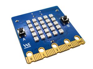
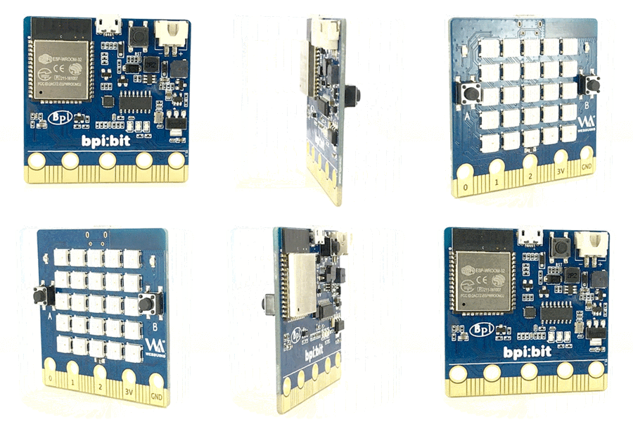
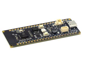
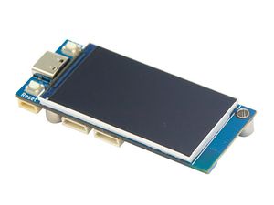
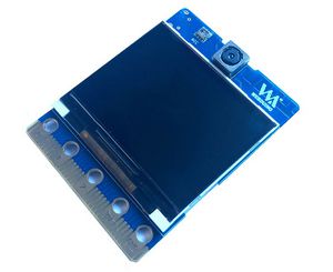
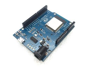
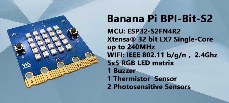
BPI-Bit-S2 development board is a successor to BPI-Bit, inheriting most of the hardware functions.
IO is compatible with micro:bit and can use most peripheral accessories of micro:bit.
Support Webduino, Arduino, MicroPython & CircuitPython programming environment suitable for STEAM education.
Key features
- ESP32-S2
- 5x5 RGB LED matrix
- 1 buzzer
- 1 thermistor sensor
- 2 photosensitive sensors
- 2 programmable keys,1 BOOT key,1 Reset key
- Type-C USB interface
- Size 5x5cm
- The Goldfinger Edge Connector definition is fully compatible with Micro: Bit
Feature comparison
| micro:bit vs BPI-Bit-S2 | ||
|---|---|---|
| Product | micro:bit V2.2X | BPI-Bit-S2 |
| MCU | Nordic nRF52833 | Espressif ESP32-S2 |
| Frequency | 64MHz | 240MHz |
| RAM | 128KB | 320 KB |
| FlASH ROM | 512KB | 4096 KB |
| PSRAM | None | 2048 KB |
| Wireless Communication | Bluetooth,microbit-radio | WIFI, IEEE 802.11 b/g/n, 2.4Ghz |
| LED | 25 red LEDs | 25 WS2812-3535 RGB LEDs |
| Key | 2 programmable keys, 1 RST key | 2 programmable keys, 1 BOOT key, 1 RST key |
| Buzzer | Yes | Yes |
| Microphone | Yes | None |
| USB Socket | Micro USB | Type-C USB |
| USB interface chip | nRF52833-QDAA or nRF52820-QDAA | MCU chip built-in |
| Battery socket | Yes | None |
| IO | 19 pins golden finger IO, alligator clip bayonet, support touch sensing | 19 pins golden finger IO (compatible with micro:bit), alligator clip bayonet, support touch sensing |
| Motion sensor | Yes | None |
| Photosensitive sensor | None | 2 |
| Thermistor sensor | 1 on-core | 1 on-board |
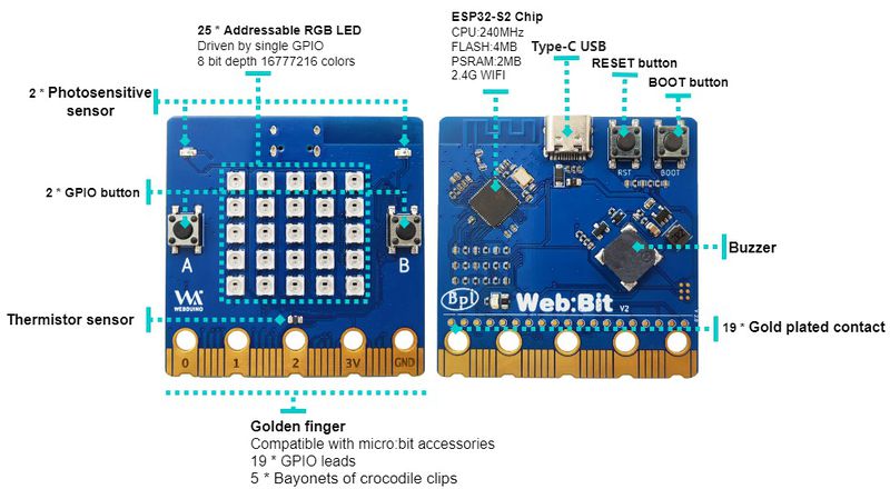
Hardware interface
| BPI-Bit-S2 specification | |
|---|---|
| MCU | ESP32-S2FN4R2,Xtensa® 32 bit LX7 Single-Core Processer |
| Frequency | 240MHz MAX |
| operating temperature | -40℃~+85℃ |
| ROM | 128 KB |
| SRAM | 320 KB |
| FLASH ROM | 4 MB |
| PSRAM | 2 MB |
| WIFI | IEEE 802.11 b/g/n ,2.4Ghz |
| GPIO | 19 available GPIO pins have been introduced |
| Peripheral functions | ADC,TOUCH,PWM,SPI,I2C,I2S,Pulse counter, RMT,TWAI® Controller,SD/MMC,LCD_CAMERA |
| External crystal | 40Mhz |
| Buzzer | 8.5x8.5mm buzzer |
| LED | 25 WS2812 rgb LED, single line GPIO control; 1 monochrome LED, controlled by GPIO0 |
| Photosensitive sensor | 2 photosensitive sensor |
| Thermistor sensor | 1 thermistor sensor |
| IO | 19 pins Goldfinger IO,19 pins contacts on the back |
| Key | 2 programmable keys,1 BOOT key,1 Reset key |
| USB | USB Type-C interface,full speed USB OTG,USB-ACM |
| Operating voltage | 3.3V |
| Power | USB Type-C input 5V,or Goldfinger IO input 3.3V power supply |
| Size | 5 * 5 cm |
On-board peripherals
| Peripheral GPIO allocation and signal type | ||
|---|---|---|
| Photosensitive sensor(L) | GPIO 12 | Analog Input |
| Photosensitive sensor(R) | GPIO 13 | Analog Input |
| Thermistor sensor | GPIO 14 | Analog Input |
| Key A | GPIO 38 | Digital Input |
| Key B | GPIO 33 | Digital Input |
| Key BOOT | GPIO 0 | Digital Input |
| Buzzer | GPIO 17 | PWM(Digital Output) |
| RGB LEDs | GPIO 18 | Digital Output |
5*5 RGB LED
BPI-Bit-S2 have 25 WS2812 full color RGB LED, single GPIO ontrol.
The three primary color pixels of each LED can achieve 8bit 256 level brightness display,
and achieve 16777216 color full color display,
scanning frequency is not less than 400Hz/s.
| 5*5 LED Sequential List | ||||
|---|---|---|---|---|
| 20 | 15 | 10 | 5 | 0 |
| 21 | 16 | 11 | 6 | 1 |
| 22 | 17 | 12 | 7 | 2 |
| 23 | 18 | 13 | 8 | 3 |
| 24 | 19 | 14 | 9 | 4 |
Goldfinger GPIO define
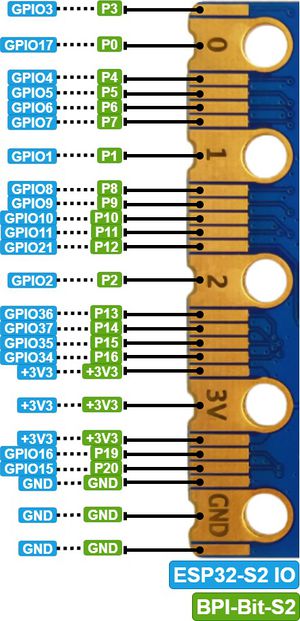
BPI-Bit-S2 Gold finger GPIO is defined to be compatible with Micro:Bit. GPIO expansion board accessories can be used with Micro: Bit.
| SPI,I2C | ||
|---|---|---|
| Function | Pin Name | GPIO Num |
| SPI_SCK | P13 | GPIO36 |
| SPI_MISO | P14 | GPIO37 |
| SPI_MOSI | P15 | GPIO35 |
| SPI_CS | P16 | GPIO34 |
| I2C_SCL | P19 | GPIO16 |
| I2C_SDA | P20 | GPIO15 |
Power
BPI-Bit-S2 supports two power supply modes
1. Type-C USB:Use USB cable power supply, connect USB interface of computer or other 5V USB charger to power the development board.
2. Gold finger: At the bottom of the development board, the gold finger contains a power interface with both input and output functions. It uses 3.3V power supply, positive terminal is connected to 3V3, and negative terminal is connected to GND.
Software
Webduino
webduino online building block programming platform
webduino building block programming platform, Windows Installer
MicroPython
MicroPython is a lean and efficient implementation of the Python 3 programming language that includes a small subset of the Python standard library and is optimised to run on microcontrollers and in constrained environments.
Crowdfunded and open sourced in 2013 by Damien P. George.
The most obvious difference between it and the use of C programs to develop microcontrollers is that there is no need for lengthy compilation when verifying code.
Using serial communication software, enter commands through the REPL(read-eval-print-loop) to control the microcontroller, just like Python's REPL.
It is also possible to use some tools to upload a python script file to run inside the microcontroller.
Its implementation of Python3 includes the _thread library that supports multithreading and the asyncio library for writing concurrent code.
MicroPython aims to be as compatible with normal Python as possible to allow you to transfer code with ease from the desktop to a microcontroller or embedded system.
At the same time it also has some libraries specific for microcontrollers in order to take full advantage of the hardware features inside the microcontroller chip, such as timers, hardware interrupts, WiFi, etc., depending on the specific hardware.
While having the above features, it is compact enough to fit and run within just 256k of code space and 16k of RAM.
If you know Python you already know MicroPython.
On the other hand, the more you learn about MicroPython the better you become at Python.
CircuitPython
CircuitPython is an open source, educational derivative of MicroPython, support and developed by Adafruit Industries.
Comparing ease of use, it goes a step further on the basis of MicroPython.
When the development board running CircuitPython firmware is connected to the PC, the PC will immediately recognize it as a USB storage disk.
And the python script file can be copied to this disk to allow the program to run on the development board.
Modern operating systems and home PCs support USB storage disks, this allows users to use it out of the box.
Of course, in order to use REPL, a serial communication software needs to be installed, or a text editor that supports this function, such as Mu editor.
The CircuitPython community provides an extremely rich peripheral driver library, APIs documentation, and tutorials.
Even if there is no programming foundation, no hardware foundation, you can quickly get started from scratch.
CircuitPython does not support some microcontroller-specific libraries such as timer and hardware interrupt, nor does it support the multi-threaded _thread library. It only provides the asyncio library for writing concurrent code.
The code is very compatible between microcontrollers supported by CircuitPython and single-board computers (SBCs) supported by Blinka. This is thanks to its efforts to unify APIs.
BPI-Bit-S2 CircuitPython Download Page
How to install tinyUF2 firmware:
To enable your BPI-Bit-S2 device to flash via USB-CDC.
Connect it to the computer via USB, hold BOOT button, press RST button once, then release BOOT button.
In the Install, Repair, or Update UF2 Bootloader section at the bottom of the page, follow its instructions to download and install tinyUF2 firmware.
How to install CircuitPython firmware:
Click the DOWNLOAD .UF2 NOW button on the right side of the page to download the firmware to the local, and then copy it to the disk in BPI-Bit-S2 UF2 Bootloader mode, and it can be used after automatic reset.
Arduino
Arduino is an open source embedded hardware and software development platform for users to create interactive embedded projects.
The Arduino integrated development environment (IDE) is the software core of this platform, using the C/C++ programming language to develop projects.
The biggest feature of Arduino is to provide a unified API to develop all microcontrollers it supports, with very good code portability and reusability.
In addition, it simplifies the process of building a development environment, and all the development environments of microcontrollers it supports can be installed and configured with a single click.
It also provides simple one-click mechanisms to compile and upload programs to a microcontroller.
Arduino IDE alsoprovides many example codes, supplemented by a large number of comments, which can help users get started quickly.
A large number of excellent open source projects accumulated in the Arduino community are available for reference and learning, and there are quite a few driver libraries and APIs provided by chip manufacturers as well.
- Arduino IDE download link | Install and configure Arduino-ESP32 running environment
- Arduino-ESP32 APIs
Documents
Easy to buy sample
- Aliexpress shop : https://www.aliexpress.us/item/3256804809903732.html
- Taobao ship: https://item.taobao.com/item.htm?spm=a213gs.success.result.1.d1187a86CepiGC&id=693462857865
- OEM & ODM : [email protected]
