Difference between revisions of "BPI-Smart"
(→BPI:Smart hardware) |
(→BPI:Smart hardware) |
||
| Line 16: | Line 16: | ||
[[File:Smart-01-02.jpg]] | [[File:Smart-01-02.jpg]] | ||
| + | |||
| + | ==Hardware interface== | ||
| + | |||
| + | BPI-Smart has a photocell sensor, an RGB LED, and a micro switch button onboard. The photocell is connected to the AD pin, and the RGB (Red, Geen, Blue) LED is connected to pins 15, 12, and 13 respectively (The LED is a common cathode, whereas most of the examples on this site use common anode RGB LED.) And the micro switch button is connected to pin 4. Please take note when you use these pins. | ||
| + | |||
| + | [[File:Smart-01-05.jpg]] | ||
=doc= | =doc= | ||
Revision as of 02:08, 9 May 2018
Contents
Introduction
BPI-Smart is a ground-breaking development board.
The BPI-Smart (also referred to as BPI:Smart, stylised as webduino:Smart) is an ESP32 with Xtensa 32bit LX6 single/dual-core processor based embedded system. support Webduino and arduino function.
BPI:Smart hardware
BPI:bit hardware description
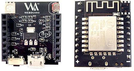
BPI-Smart Board dimensions: 3cm in length, 2.5cm in width, 1.3cm in height, and a weight of 85 grams. Digital pins: 0, 2, 4, 5, 14, and 16. PWM pins: 12, 13, 15. Analog Pin: AD \(A0\). Other pins: TX, RX, 3.3V, VCC, RST, and GRD.
The front and back images:
Hardware interface
BPI-Smart has a photocell sensor, an RGB LED, and a micro switch button onboard. The photocell is connected to the AD pin, and the RGB (Red, Geen, Blue) LED is connected to pins 15, 12, and 13 respectively (The LED is a common cathode, whereas most of the examples on this site use common anode RGB LED.) And the micro switch button is connected to pin 4. Please take note when you use these pins.
