Difference between revisions of "BPI-Nano robot board"
(→Overview) |
(→Software) |
||
| (42 intermediate revisions by 3 users not shown) | |||
| Line 2: | Line 2: | ||
=Overview= | =Overview= | ||
[[File:BPI-Nano_robort_2.JPG|thumb|arduino Nano robot board]] | [[File:BPI-Nano_robort_2.JPG|thumb|arduino Nano robot board]] | ||
| − | [[File:BPI- | + | [[File:BPI-Nano_robort_3.JPG|thumb| BPI-Nano arduino Nano]] |
| + | [[File:BPI-Nano_robort_4.JPG|thumb| BPI-Nano arduino Nano]] | ||
| + | [[File:BPI-Nano_robort_6.JPG|thumb| with [[BPI-NANO arduino NANO board ]]]] | ||
| + | [[File:BPI-Nano_1.JPG|thumb|[[BPI-NANO arduino NANO board ]]]] | ||
| + | [[File:BPI-UNO_1.JPG|thumb|[[BPI-UNO arduino UNO board]]]] | ||
| + | [[File:ESP32_6.JPG|thumb|[[BPI-UNO32]] with ESP32]] | ||
| + | |||
| + | This robot board is design for Arduino Nano and Nano compatible boards. It is designed by [https://www.facebook.com/harsh.dethe.5602 '''Harsh Dethe'''] and made by [http://wiki.banana-pi.org/About_BPI '''BPI factory''']. | ||
| + | |||
| + | BPI-Nano robot board's motor drive expansion plate available in the bpi-nano controller supports dual-circuit motor control, with single maximum current up to 1A. | ||
| + | |||
| + | Arduino standard pin design interface, also can be used with Arduino Nano. It can be use for the development of small mobile robots. | ||
=Hardware= | =Hardware= | ||
| + | ==Technical specifications== | ||
| + | *Driver chip: L293B | ||
| + | *Logical working voltage: 5V DC | ||
| + | *Motor drive voltage: 7-12v DC | ||
| + | *Maximum driving current: 1A (per circuit) | ||
| + | *Pin for motor drive: pin4/5/6/7 (Arduino controller) | ||
| + | *Size: 75mmx45mm | ||
| + | |||
| + | ==Hardware interface== | ||
| + | |||
| + | [[File:BPI-Nano_robort_interface.png]] | ||
| + | |||
| + | [[File:BPI-Nano_robort_interface_1.png]] | ||
| + | |||
| + | ==PIN define== | ||
| + | |||
| + | {| class="wikitable" | ||
| + | |- | ||
| + | | style="background: PaleTurquoise; color: black" colspan="4"| '''BPI-Nano aruino Nano robort GPIO pin define''' | ||
| + | |- | ||
| + | |Pin ||Function | ||
| + | |- | ||
| + | |Digital 2、4 ||Motor2 Steering control, 2 high level, 4 low level positive turn;Whereas inversion | ||
| + | |- | ||
| + | |Digital 3 ||Motor 2 Enable interface, high level enable | ||
| + | |- | ||
| + | |Digital 5 ||Motor 1 Enable interface, high level enable | ||
| + | |- | ||
| + | |Digital 7、8 ||Motor 1 Steering control, 7 high level, 8 low level positive turn;Whereas inversion | ||
| + | |- | ||
| + | |} | ||
=Software= | =Software= | ||
| + | ==Sample code== | ||
| + | |||
| + | //This motor shield use Pin 2,3,4,5,6,7,8 to control the motor | ||
| + | // Just plug the nano into the shield | ||
| + | // Simply connect your motors to M1 ,M2 | ||
| + | // Upload the code to BPI-NANO/arduino | ||
| + | // Through serial monitor, type 'a','s', 'w','d','x' to control the motor | ||
| + | // http://www.banana-pi.org/ | ||
| + | // http://www.banana-pi.org/ | ||
| + | // Last modified on 20/09/2019 | ||
| + | int EN1 = 5; //Motor 1 Enable | ||
| + | int EN2 = 3; //Motor 2 Enable | ||
| + | int IN1 = 7; | ||
| + | int IN2 = 8; //Motor 1 | ||
| + | int IN3 = 2; | ||
| + | int IN4 = 4; //Motor 2 | ||
| + | void Motor1(int ENA, boolean reverse) | ||
| + | { | ||
| + | digitalWrite(ENA,HIGH); | ||
| + | if(reverse) | ||
| + | { | ||
| + | digitalWrite(IN1,HIGH); | ||
| + | digitalWrite(IN2,LOW); | ||
| + | } | ||
| + | else | ||
| + | { | ||
| + | digitalWrite(IN1,LOW); | ||
| + | digitalWrite(IN1,HIGH); | ||
| + | } | ||
| + | } | ||
| + | void Motor2(int ENB, boolean reverse) | ||
| + | { | ||
| + | digitalWrite(ENB,HIGH); | ||
| + | if(reverse) | ||
| + | { | ||
| + | digitalWrite(IN3,HIGH); | ||
| + | digitalWrite(IN4,LOW); | ||
| + | } | ||
| + | else | ||
| + | { | ||
| + | digitalWrite(IN3,LOW); | ||
| + | digitalWrite(IN4,HIGH); | ||
| + | } | ||
| + | } | ||
| + | void setup() | ||
| + | { | ||
| + | int i; | ||
| + | for(i=2;i<=8;i++) //For BPI-NANO Motor Shield | ||
| + | pinMode(i, OUTPUT); //set pin 2,3,4,5,6,78 to output mode | ||
| + | Serial.begin(9600); | ||
| + | } | ||
| + | void loop() | ||
| + | { | ||
| + | int x,delay_en; | ||
| + | char val; | ||
| + | while(1) | ||
| + | { | ||
| + | val = Serial.read(); | ||
| + | if(val!=-1) | ||
| + | { | ||
| + | switch(val) | ||
| + | { | ||
| + | case 'w'://Move ahead | ||
| + | Motor1(100,true); | ||
| + | Motor2(100,true); | ||
| + | break; | ||
| + | case 's'://move back | ||
| + | Motor1(100,false); | ||
| + | Motor2(100,false); | ||
| + | break; | ||
| + | case 'a'://turn left | ||
| + | Motor1(100,true); | ||
| + | Motor2(100,false); | ||
| + | break; | ||
| + | case 'd'://turn right | ||
| + | Motor1(100,false); | ||
| + | Motor2(100,true); | ||
| + | break; | ||
| + | case 'x'://stop | ||
| + | digitalWrite(ENA,LOW); | ||
| + | digitalWrite(ENB,LOW); | ||
| + | break; | ||
| + | } | ||
| + | } | ||
| + | } | ||
| + | } | ||
| + | |||
| + | =Documents= | ||
| + | |||
| + | *BPI-Nano Robort board DXF file : https://drive.google.com/file/d/1fDHVvQVRJTQIe-0UDMrpL-HiYb9qPaZ4/view?usp=sharing | ||
| + | |||
| + | =Easy to buy sample= | ||
| + | |||
| + | *aliexpress ship : https://www.aliexpress.com/item/4000244997068.html?spm=2114.12010612.8148356.1.7f5121dajc1zAc | ||
| + | *Welcome for OEM&ODM | ||
Latest revision as of 20:48, 8 November 2019
Contents
Overview
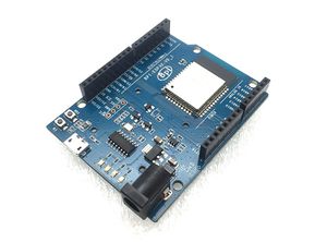
BPI-UNO32 with ESP32
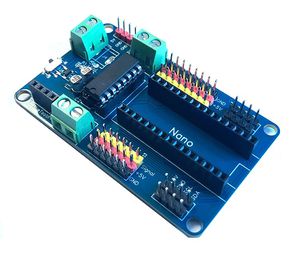
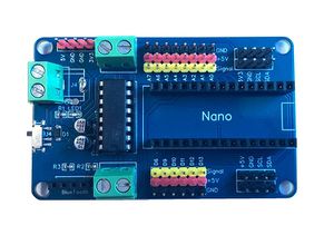
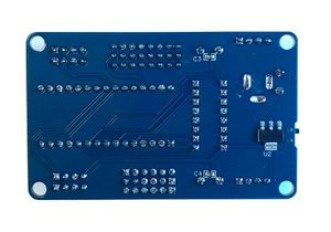
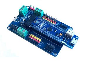
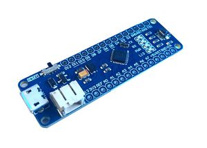
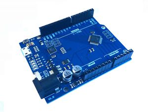
This robot board is design for Arduino Nano and Nano compatible boards. It is designed by Harsh Dethe and made by BPI factory.
BPI-Nano robot board's motor drive expansion plate available in the bpi-nano controller supports dual-circuit motor control, with single maximum current up to 1A.
Arduino standard pin design interface, also can be used with Arduino Nano. It can be use for the development of small mobile robots.
Hardware
Technical specifications
- Driver chip: L293B
- Logical working voltage: 5V DC
- Motor drive voltage: 7-12v DC
- Maximum driving current: 1A (per circuit)
- Pin for motor drive: pin4/5/6/7 (Arduino controller)
- Size: 75mmx45mm
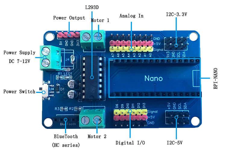
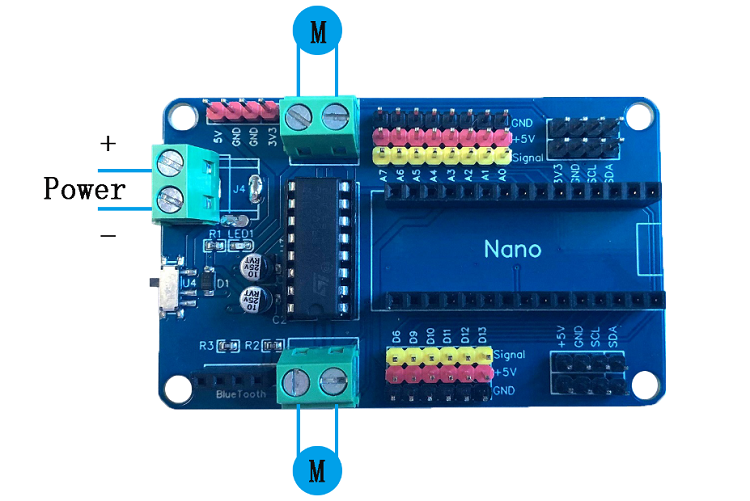
Hardware interface
PIN define
| BPI-Nano aruino Nano robort GPIO pin define | |||
| Pin | Function | ||
| Digital 2、4 | Motor2 Steering control, 2 high level, 4 low level positive turn;Whereas inversion | ||
| Digital 3 | Motor 2 Enable interface, high level enable | ||
| Digital 5 | Motor 1 Enable interface, high level enable | ||
| Digital 7、8 | Motor 1 Steering control, 7 high level, 8 low level positive turn;Whereas inversion | ||
Software
Sample code
//This motor shield use Pin 2,3,4,5,6,7,8 to control the motor
// Just plug the nano into the shield
// Simply connect your motors to M1 ,M2
// Upload the code to BPI-NANO/arduino
// Through serial monitor, type 'a','s', 'w','d','x' to control the motor
// http://www.banana-pi.org/
//  http://www.banana-pi.org/
// Last modified on 20/09/2019
int EN1 = 5;  //Motor 1 Enable
int EN2 = 3;  //Motor 2 Enable
int IN1 = 7;
int IN2 = 8; //Motor 1
int IN3 = 2;
int IN4 = 4; //Motor 2
void Motor1(int ENA, boolean reverse)
       {
         digitalWrite(ENA,HIGH);
        if(reverse)
        {
         digitalWrite(IN1,HIGH);
         digitalWrite(IN2,LOW);
        }
       else
       {
         digitalWrite(IN1,LOW);
         digitalWrite(IN1,HIGH);
        }
       }
void Motor2(int ENB, boolean reverse)
       {
         digitalWrite(ENB,HIGH);
        if(reverse)
        {
         digitalWrite(IN3,HIGH);
         digitalWrite(IN4,LOW);
        }
       else
       {
         digitalWrite(IN3,LOW);
         digitalWrite(IN4,HIGH);
        }
       }
void setup()
{
   int i;
   for(i=2;i<=8;i++)  //For BPI-NANO Motor Shield
   pinMode(i, OUTPUT);  //set pin 2,3,4,5,6,78 to output mode
   Serial.begin(9600);
}
void loop()
{
 int x,delay_en;
 char val;
 while(1)
 {
   val = Serial.read();
   if(val!=-1)
      {
         switch(val)
          {
            case 'w'://Move ahead
                       Motor1(100,true);
                       Motor2(100,true);
                        break;
            case 's'://move back
                       Motor1(100,false);
                       Motor2(100,false);
                        break;
            case 'a'://turn left
                       Motor1(100,true);
                       Motor2(100,false);
                        break;
            case 'd'://turn right
                       Motor1(100,false);
                       Motor2(100,true);
                       break;
              case 'x'://stop
                       digitalWrite(ENA,LOW);
                       digitalWrite(ENB,LOW);
                        break;
          }
      }
  }
}
Documents
- BPI-Nano Robort board DXF file : https://drive.google.com/file/d/1fDHVvQVRJTQIe-0UDMrpL-HiYb9qPaZ4/view?usp=sharing
Easy to buy sample
- aliexpress ship : https://www.aliexpress.com/item/4000244997068.html?spm=2114.12010612.8148356.1.7f5121dajc1zAc
- Welcome for OEM&ODM
