Difference between pages "BPI-Bit" and "Getting Started with M64"
(Difference between pages)
(→Introduction) |
JackZengWiki (talk | contribs) (→Introduction) |
||
| Line 1: | Line 1: | ||
| + | =Introduction= | ||
| + | ==BPI-M2M== | ||
| + | [[File:M64_respbian.png|thumb|Overview: BPI-M64 respbian linux]] | ||
| − | + | Banana Pi BPI-M64 is a 64-bit quad-core mini single board computer. It features 2GB of RAM and 8GB eMMC. It also has onboard WiFi and BT. On the ports side, the BPI-M64 has 2 USB A 2.0 ports, 1 USB OTG port, 1 HDMI port, 1 audio jack, and lastly a DC power port. The processor is pin-to-pin comptialbe with R18, so it comes with two versions:M64 and M64-R18 | |
| − | + | *Read more about : [[Banana Pi BPI-M64]] | |
| − | |||
| − | [[ | ||
| − | + | ===A64 Key Features=== | |
| + | * 1.2 Ghz Quad-Core ARM Cortex A53 64-Bit Processor-A64 | ||
| + | * 2GB DDR3 SDRAM | ||
| + | * 8G EMMC | ||
| + | * 10/100/1000Mbps Ethernet | ||
| + | * WiFi (AP6212) & Bluetooth | ||
| − | + | ===R18 Key Features=== | |
| + | * 1.2 Ghz Quad-Core ARM Cortex A53 64-Bit Processor-R18 | ||
| + | * 2GB DDR3 SDRAM | ||
| + | * 8G EMMC | ||
| + | * 10/100/1000Mbps Ethernet | ||
| + | * WiFi (AP6212) & Bluetooth | ||
| − | + | =Development= | |
| + | ==Basic Development== | ||
| + | ===Prepare to develop=== | ||
| + | * Prepare 8G/above TF card, USB-Serial interface, PC with Ubuntu System | ||
| + | * Using your USB-Serial Connect debug console on M64 | ||
| − | bpi: | + | ===Load your first image on M64=== |
| + | 1.You could download latest image from our forum | ||
| + | |||
| + | 2.Install bpi-tools on your system | ||
| + | * apt-get install pv | ||
| + | * curl -sL https://github.com/BPI-SINOVOIP/bpi-tools/raw/master/bpi-tools | sudo -E bash | ||
| + | |||
| + | 3.After you download the image, insert your TF card into your Ubuntu | ||
| + | * Execute "bpi-copy xxx.img /dev/sdx" to install image on your TF card. | ||
| + | |||
| + | 4.After step 3, then you can insert your TF card into M64, and press power button setup M64 | ||
| − | + | ===Load your first image on M64 EMMC=== | |
| − | * | + | * Run your M64 with TF card |
| − | * | + | * Copy "xxx-sd-emmc-xxx.img.zip / xxx-sd-emmc-xxx.img" to your USB disk |
| − | * | + | * Plug your USB disk in M2U |
| − | * | + | * After M64 recognise USB disk, execute "bpi-copy xxx-sd-emmc-xxx.img.zip / xxx-sd-emmc-xxx.img" to install image on EMMC |
| − | * | + | * Then power off M64, take TF card out, power on M64 |
| − | = | + | ==Advanced Development== |
| + | ===How to build uboot & kernel=== | ||
| + | ====Install tools==== | ||
| + | * apt-get udpate | ||
| + | * apt-get install gcc-arm-linux-gnueabihf u-boot-tools | ||
| + | * apt-get install pv | ||
| + | * curl -sL https://github.com/BPI-SINOVOIP/bpi-tools/raw/master/bpi-tools | sudo -E bash | ||
| − | == | + | ===SATA=== |
| + | 1. Mount SATA on M2U | ||
| − | + | [[Image:A64_Sata.png]] | |
| − | + | * After insert sata interface, execute "fdisk -l" | |
| + | [[Image:A64_Sata_fdisk_l.png]] | ||
| − | + | * Then "mount /dev/sdx /mnt/xxx" | |
| − | + | 2. If you meet some errors when you mount SATA, try these following commands: | |
| − | + | * "fdisk /dev/sdx" to create new partition , set your partition numbers and size, after created partitions, input "wq" to save and quit. | |
| + | * "mkfs.ext2 /dev/sdx" to format the SATA | ||
| + | * "mount /dev/sdx /mnt/xxx" | ||
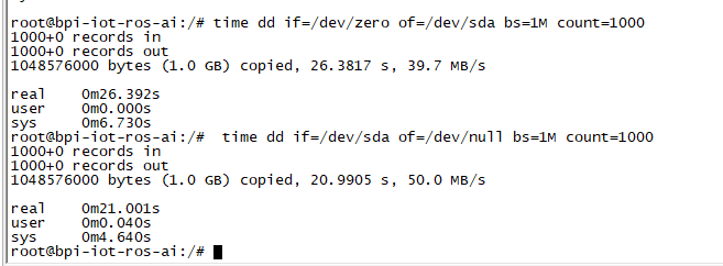
| − | == | + | 3. After you success to insert SATA, we could input following commands to test SATA interface: |
| + | * "time dd if=/dev/xxx of=/dev/null bs=1M count=1000" to test read speed | ||
| + | * "time dd if=/dev/zero of=/dev/sdx bs=1M count=1000" to test write speed | ||
| + | [[Image:Sata_test.png]] | ||
| − | |||
| − | == | + | ===LCD 5" & LCD 7"=== |
| + | * Execute "bpi-bootsel", you'll see a list of boot files | ||
| + | * Find "BPI_A64_LCD7.img.gz" | ||
| + | * Then execute "bpi-bootsel /usr/lib/u-boot/bananapi/bpi-m64/u-boot-with-dtb-bpi-m64-lcd7-8k.img.gz" | ||
| + | [[Image:A64_bootsel_lcd7.png]] | ||
| − | + | ===Touch screen=== | |
| − | + | ===GMAC=== | |
| − | + | Use iperf3 to test gmac | |
| − | |||
| − | |||
| − | |||
| − | |||
| − | |||
| − | |||
| − | |||
| − | |||
| − | |||
| − | |||
| − | |||
| − | |||
| − | |||
| − | |||
| − | |||
| − | |||
| − | |||
| − | |||
| − | |||
| − | |||
| − | |||
| − | |||
| − | |||
| − | |||
| − | |||
| − | |||
| − | |||
| − | |||
| − | |||
| − | |||
| − | |||
| − | |||
| − | |||
| − | |||
| − | |||
| − | |||
| − | |||
| − | |||
| − | |||
| − | |||
| − | |||
| − | |||
| − | |||
| − | |||
| − | |||
| − | |||
| − | |||
| − | |||
| − | |||
| − | |||
| − | |||
| − | |||
| − | |||
| − | |||
| − | |||
| − | + | 1. On PC Terminal: | |
| − | + | * Execute "iperf3 -s" | |
| − | |||
| − | |||
| − | |||
| − | |||
| − | |||
| − | |||
| − | |||
| − | |||
| − | |||
| − | |||
| − | |||
| − | |||
| − | |||
| − | |||
| − | |||
| − | + | 2. On M2U console: | |
| − | + | * TCP test: "iperf3 -c serverIP" | |
| + | * UDP test: "iperf3 -u -c serverIP" | ||
| + | [[Image:A64_Gmac_test.png]] | ||
| − | + | ===Bluetooth=== | |
| + | * Use bluetoothctl tool to operate BT | ||
| + | * Execute "bluetoothctl" | ||
| + | * If you don't know how to use bluetoothctl, type "help", you will see more commands | ||
| + | * Execute these commands: | ||
| + | [[Image:A64_bluetooth.png]] | ||
| + | ===WiFi on A64=== | ||
| + | ====WiFi Client==== | ||
| + | '''You have two ways to setup WiFi Client''' | ||
| + | 1. Use commands to setup WiFi client | ||
| + | * ip link set wlan0 up | ||
| + | * iw dev wlan0 scan | grep SSID | ||
| + | * vim /etc/wpasupplicant/wpa_supplicant.conf | ||
| + | * network={ ssid="ssid" psk="password" priority=1 } | ||
| + | * wpa_supplicant -B -dd -i wlan0 -c /etc/wpa_supplicant/wpa_supplicant.conf | ||
| + | * dhclient wlan0 | ||
| − | + | 2. Use UI interface to setup WiFi Client | |
| − | == | + | ===Clear boot=== |
| + | * git clone https://github.com/BPI-SINOVOIP/BPI-files/tree/master/SD/100MB | ||
| + | * bpi-bootsel BPI-cleanboot-8k.img.gz /dev/sdX | ||
| − | === | + | ===Camara function=== |
| − | + | We use HDF5640 camara. | |
| − | [[ | + | [[Image:ov5640_camara.png]] |
| + | ====Guvcview==== | ||
| + | * Use your UI interface to operate camara | ||
| + | * Applications -> Sound & Video -> guvcview | ||
| + | ====Shell==== | ||
| + | * We also have built-in command in "/usr/local/bin" to test camara | ||
| + | * "./test_ov5640_image_mode.sh" to test picture taking function | ||
| + | * "./cameratest.sh" to test video recording function | ||
| − | + | ===IR function=== | |
| + | * Execute "getevent" | ||
| + | * Use your IR device to send information to A64 | ||
| − | * | + | ===WringPi=== |
| − | + | * GitHub: https://github.com/BPI-SINOVOIP/BPI-WiringPi2.git | |
| − | * | + | * We also have built-in test command in "/usr/local/bin" |
| − | + | ====RGB 1602 LCD==== | |
| + | * Execute "/usr/local/bin/bpi_test_lcd1602.sh" | ||
| − | === | + | ====0.96 Inch OLED Display==== |
| − | * | + | * Execute "/usr/local/bin/bpi_test_52pi.sh" |
| − | |||
| − | |||
| − | * | + | ====8x8 RGB LED Martix==== |
| − | : | + | * Firstly you need a GPIO Extend Board for 8x8 LED Martix |
| + | [[Image: WringPi_LED_Martix_Extend_Board.png]] | ||
| − | + | * Execute "/usr/local/bin/bpi_test_gpio40.sh" | |
| − | + | ===File System=== | |
| + | * read only system change to read & write mode: "mount -o remount,rw /" | ||
| − | + | ==FAQ== | |
| − | |||
| − | === | ||
| − | |||
| − | |||
| − | |||
| − | |||
| − | |||
| − | |||
| − | |||
| − | |||
| − | |||
| − | |||
| − | |||
| − | |||
| − | |||
| − | |||
| − | |||
| − | |||
| − | |||
| − | |||
| − | |||
| − | |||
| − | |||
| − | |||
| − | |||
| − | |||
| − | |||
| − | |||
| − | |||
| − | |||
| − | |||
| − | |||
| − | |||
| − | |||
| − | |||
| − | |||
| − | |||
| − | |||
| − | |||
| − | |||
| − | |||
| − | |||
| − | |||
| − | |||
| − | |||
| − | |||
| − | |||
| − | |||
| − | |||
| − | |||
| − | |||
| − | |||
| − | |||
| − | |||
| − | |||
| − | |||
| − | |||
| − | |||
| − | |||
| − | |||
| − | |||
| − | |||
| − | |||
| − | |||
| − | |||
| − | |||
| − | |||
| − | |||
| − | |||
| − | |||
| − | |||
| − | |||
| − | |||
| − | |||
| − | |||
| − | |||
| − | |||
| − | |||
| − | |||
| − | |||
| − | |||
| − | |||
| − | |||
| − | |||
| − | |||
| − | |||
| − | |||
| − | |||
| − | |||
| − | |||
| − | |||
| − | |||
| − | |||
| − | |||
| − | |||
| − | |||
| − | |||
| − | |||
| − | |||
| − | |||
| − | |||
| − | |||
| − | |||
| − | |||
| − | |||
| − | |||
| − | |||
| − | |||
| − | |||
| − | |||
| − | |||
| − | |||
| − | |||
| − | |||
| − | |||
| − | |||
| − | |||
| − | |||
| − | |||
| − | |||
| − | |||
| − | |||
| − | |||
| − | |||
| − | |||
| − | |||
| − | |||
| − | |||
| − | |||
| − | |||
| − | |||
| − | |||
| − | |||
| − | |||
| − | |||
| − | |||
| − | |||
| − | |||
| − | |||
| − | |||
| − | |||
| − | |||
| − | |||
| − | |||
| − | |||
| − | |||
| − | |||
| − | |||
| − | |||
| − | |||
| − | |||
| − | |||
| − | |||
| − | |||
| − | |||
| − | |||
| − | |||
| − | |||
| − | |||
| − | |||
| − | |||
| − | |||
| − | |||
| − | |||
| − | |||
| − | |||
| − | |||
| − | |||
| − | |||
| − | |||
| − | |||
| − | |||
| − | |||
| − | |||
| − | |||
| − | |||
| − | |||
| − | |||
| − | |||
| − | |||
| − | |||
| − | |||
| − | |||
| − | |||
| − | |||
| − | |||
| − | |||
| − | |||
| − | |||
| − | |||
| − | |||
| − | |||
| − | |||
| − | |||
| − | |||
| − | |||
| − | |||
| − | |||
| − | |||
| − | |||
| − | |||
| − | |||
| − | |||
| − | |||
| − | |||
| − | |||
| − | |||
| − | |||
| − | |||
| − | |||
Revision as of 00:28, 29 May 2018
Contents
- 1 Introduction
- 2 Development
Introduction
BPI-M2M

Banana Pi BPI-M64 is a 64-bit quad-core mini single board computer. It features 2GB of RAM and 8GB eMMC. It also has onboard WiFi and BT. On the ports side, the BPI-M64 has 2 USB A 2.0 ports, 1 USB OTG port, 1 HDMI port, 1 audio jack, and lastly a DC power port. The processor is pin-to-pin comptialbe with R18, so it comes with two versions:M64 and M64-R18
- Read more about : Banana Pi BPI-M64
A64 Key Features
- 1.2 Ghz Quad-Core ARM Cortex A53 64-Bit Processor-A64
- 2GB DDR3 SDRAM
- 8G EMMC
- 10/100/1000Mbps Ethernet
- WiFi (AP6212) & Bluetooth
R18 Key Features
- 1.2 Ghz Quad-Core ARM Cortex A53 64-Bit Processor-R18
- 2GB DDR3 SDRAM
- 8G EMMC
- 10/100/1000Mbps Ethernet
- WiFi (AP6212) & Bluetooth
Development
Basic Development
Prepare to develop
 * Prepare 8G/above TF card, USB-Serial interface, PC with Ubuntu System
 * Using your USB-Serial Connect debug console on M64
Load your first image on M64
 1.You could download latest image from our forum

 2.Install bpi-tools on your system
 * apt-get install pv
 * curl -sL https://github.com/BPI-SINOVOIP/bpi-tools/raw/master/bpi-tools | sudo -E bash

 3.After you download the image, insert your TF card into your Ubuntu
 * Execute "bpi-copy xxx.img /dev/sdx" to install image on your TF card.

 4.After step 3, then you can insert your TF card into M64, and press power button setup M64
Load your first image on M64 EMMC
 * Run your M64 with TF card
 * Copy "xxx-sd-emmc-xxx.img.zip / xxx-sd-emmc-xxx.img" to your USB disk
 * Plug your USB disk in M2U
 * After M64 recognise USB disk, execute "bpi-copy xxx-sd-emmc-xxx.img.zip / xxx-sd-emmc-xxx.img" to install image on EMMC
 * Then power off M64, take TF card out, power on M64
Advanced Development
How to build uboot & kernel
Install tools
- apt-get udpate
- apt-get install gcc-arm-linux-gnueabihf u-boot-tools
- apt-get install pv
- curl -sL https://github.com/BPI-SINOVOIP/bpi-tools/raw/master/bpi-tools | sudo -E bash
SATA
1. Mount SATA on M2U
File:A64 Sata.png
- After insert sata interface, execute "fdisk -l"
File:A64 Sata fdisk l.png
- Then "mount /dev/sdx /mnt/xxx"
2. If you meet some errors when you mount SATA, try these following commands:
- "fdisk /dev/sdx" to create new partition , set your partition numbers and size, after created partitions, input "wq" to save and quit.
- "mkfs.ext2 /dev/sdx" to format the SATA
- "mount /dev/sdx /mnt/xxx"
3. After you success to insert SATA, we could input following commands to test SATA interface:
- "time dd if=/dev/xxx of=/dev/null bs=1M count=1000" to test read speed
- "time dd if=/dev/zero of=/dev/sdx bs=1M count=1000" to test write speed

LCD 5" & LCD 7"
- Execute "bpi-bootsel", you'll see a list of boot files
- Find "BPI_A64_LCD7.img.gz"
- Then execute "bpi-bootsel /usr/lib/u-boot/bananapi/bpi-m64/u-boot-with-dtb-bpi-m64-lcd7-8k.img.gz"

Touch screen
GMAC
Use iperf3 to test gmac
1. On PC Terminal:
- Execute "iperf3 -s"
2. On M2U console:
- TCP test: "iperf3 -c serverIP"
- UDP test: "iperf3 -u -c serverIP"

Bluetooth
- Use bluetoothctl tool to operate BT
- Execute "bluetoothctl"
- If you don't know how to use bluetoothctl, type "help", you will see more commands
- Execute these commands:

WiFi on A64
WiFi Client
You have two ways to setup WiFi Client
1. Use commands to setup WiFi client
- ip link set wlan0 up
- iw dev wlan0 scan | grep SSID
- vim /etc/wpasupplicant/wpa_supplicant.conf
- network={ ssid="ssid" psk="password" priority=1 }
- wpa_supplicant -B -dd -i wlan0 -c /etc/wpa_supplicant/wpa_supplicant.conf
- dhclient wlan0
2. Use UI interface to setup WiFi Client
Clear boot
- git clone https://github.com/BPI-SINOVOIP/BPI-files/tree/master/SD/100MB
- bpi-bootsel BPI-cleanboot-8k.img.gz /dev/sdX
Camara function
We use HDF5640 camara.

Guvcview
- Use your UI interface to operate camara
- Applications -> Sound & Video -> guvcview
Shell
- We also have built-in command in "/usr/local/bin" to test camara
- "./test_ov5640_image_mode.sh" to test picture taking function
- "./cameratest.sh" to test video recording function
IR function
- Execute "getevent"
- Use your IR device to send information to A64
WringPi
- GitHub: https://github.com/BPI-SINOVOIP/BPI-WiringPi2.git
- We also have built-in test command in "/usr/local/bin"
RGB 1602 LCD
- Execute "/usr/local/bin/bpi_test_lcd1602.sh"
0.96 Inch OLED Display
- Execute "/usr/local/bin/bpi_test_52pi.sh"
8x8 RGB LED Martix
- Firstly you need a GPIO Extend Board for 8x8 LED Martix

- Execute "/usr/local/bin/bpi_test_gpio40.sh"
File System
- read only system change to read & write mode: "mount -o remount,rw /"