Difference between revisions of "BPI AD/DA extend module"
(Created page with "# BPI AD/DA extend module  **Product Specification:**  **Produce Overview:** The DA/AD module is specifically designed for Banana...") |
(→Schematic diagram) |
||
| (4 intermediate revisions by the same user not shown) | |||
| Line 1: | Line 1: | ||
| − | |||
| − | |||
| − | |||
| − | + | =Produce Overview= | |
| − | + | [[File:AD_DA_module_1.JPG|thumb|Overview ]] | |
| − | |||
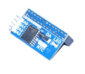
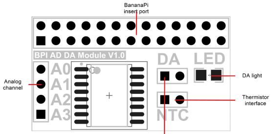
The DA/AD module is specifically designed for BananaPi. It communicated with BananaPi through I2C bus. There is a LED light on the board that you can adjust brightness through DA. The module supply 4 ADC channel through header on the left side of module and the thermistor interface. The user can choose according to actual demand and use them. The module is easy to use even you don’t need to write C code. Because the module support wiringPi so you can use shell script to control it. | The DA/AD module is specifically designed for BananaPi. It communicated with BananaPi through I2C bus. There is a LED light on the board that you can adjust brightness through DA. The module supply 4 ADC channel through header on the left side of module and the thermistor interface. The user can choose according to actual demand and use them. The module is easy to use even you don’t need to write C code. Because the module support wiringPi so you can use shell script to control it. | ||
| + | The PCF8591 is a single-chip, single-supply low-power 8-bit CMOS data acquisition device with four analog inputs, one analog output and a serial I2C-bus interface. Three address pins A0, A1 and A2 are used for programming the hardware address, allowing the use of up to eight devices connected to the I2C-bus without additional hardware. Address, control and data to and from the device are transferred serially via the two-line bidirectional I2C-bus. | ||
| − | + | The functions of the device include analog input multiplexing, on-chip track and hold function, 8-bit analog-to-digital conversion and an 8-bit digital-to-analog conversion. The maximum conversion rate is given by the maximum speed of the I2C-bus. | |
| − | |||
| − | |||
| − | |||
| − | |||
| − | |||
| − | + | ==Product Specification== | |
| − | |||
| − | |||
| − | |||
| − | |||
| − | + | [[File:Adda1.png]] | |
| − | |||
| − | |||
| − | |||
| − | |||
| − | |||
| − | |||
| − | |||
| − | ** | + | ==Produce Features== |
| + | *1. Use PCF8591T chip | ||
| + | *2. DA/AD in one module | ||
| + | *3. 8bit high resolution DA/AD | ||
| + | *4. Compatible with wiringPi | ||
| + | *5. Supply thermistor and photoresistance | ||
| − | 1. | + | ==Port== |
| − | 2. | + | *1. Banana Pi connection port,also can use on raspberry pi. |
| − | 3. | + | *2. 4 external analog channel |
| + | *3. Electric level switch jumper | ||
| + | *4. LED of DA choice jumper | ||
| − | ** | + | ==Product Parameters== |
| + | *1. Working voltage: 2.5V-6.0V | ||
| + | *2. 8-bit successive approximation A/D conversion | ||
| + | *3. Multiplying DAC with one analog output | ||
| + | *4. Analog voltage range from Vss to VDD | ||
| + | *5. 4 analog inputs configurable as single ended or differential inputs | ||
| + | *6. Max sampling rate given by I2C-bus speed | ||
| + | *7. −40°C to +85°C operation | ||
| + | |||
| + | ==Typical Application== | ||
| + | |||
| + | *1. Supply monitoring | ||
| + | *2. Reference setting | ||
| + | *3. Analog control loop | ||
| + | |||
| + | ==Testbench== | ||
| + | *1. Set the DA jumper close | ||
| + | *2. Power up the BananaPi and install Bananabian | ||
| + | *3. Install the wiringPi | ||
| + | *4. Input the command in Terminal: gpio -x pcf8591:120:0x48 awrite 120 127 | ||
| + | *5. If the LED have the half brightness the module is OK | ||
Just insert the module to Banana Pi, like the below picture: | Just insert the module to Banana Pi, like the below picture: | ||
| − | + | [[File:Adda2.png]] | |
| − | |||
| − | + | D/A conversion sequence:** | |
| − | |||
| − | + | [[File:Adda3.png]] | |
| − | |||
| − | |||
| − | + | A/D conversion sequence:** | |
| − | + | [[File:Adda4.png]] | |
| − | + | ==Schematic diagram== | |
| − | + | [[File:Adda5.png]] | |
| − | + | =How to use= | |
| − | + | ==How to use AD/DA module on BPI-M3== | |
 |  | ||
Step 1: Download WiringPI | Step 1: Download WiringPI | ||
| − | + | ||
| − | $ git clone https://github.com/BPI-SINOVOIP/BPI-WiringPi.git111 -b BPI_M3 | + | $ git clone https://github.com/BPI-SINOVOIP/BPI-WiringPi.git111 -b BPI_M3 |
| − | $ cd BPI-WiringPi | + | $ cd BPI-WiringPi |
| − | $ chmod +x ./build | + | $ chmod +x ./build |
| − | $ sudo ./build | + | $ sudo ./build |
| − | + | ||
Step 2:Check the BPI I2C GPIO extend(PCF8591T) device to see if it's on track.(address 0x48) | Step 2:Check the BPI I2C GPIO extend(PCF8591T) device to see if it's on track.(address 0x48) | ||
| + | |||
(I2c port number for M3: 2 ) | (I2c port number for M3: 2 ) | ||
| − | + | sudo su | |
| − | sudo su | + | i2cdetect -y 2 |
| − | i2cdetect -y 2 | + | . 0 1 2 3 4 5 6 7 8 9 a b c d e f |
| − | . 0 1 2 3 4 5 6 7 8 9 a b c d e f | + | 00: -- -- -- -- -- -- -- -- -- -- -- -- -- |
| − | 00: -- -- -- -- -- -- -- -- -- -- -- -- -- | + | 10: -- -- -- -- -- -- -- -- -- -- -- -- -- -- -- -- |
| − | 10: -- -- -- -- -- -- -- -- -- -- -- -- -- -- -- -- | + | 20: -- -- -- -- -- -- -- -- -- -- -- -- -- -- -- -- |
| − | 20: -- -- -- -- -- -- -- -- -- -- -- -- -- -- -- -- | + | 30: -- -- -- -- -- -- -- -- -- -- -- -- -- -- -- -- |
| − | 30: -- -- -- -- -- -- -- -- -- -- -- -- -- -- -- -- | + | 40: -- -- -- -- -- -- -- -- 48 -- -- -- -- -- -- -- |
| − | 40: -- -- -- -- -- -- -- -- 48 -- -- -- -- -- -- -- | + | 50: -- -- -- -- -- -- -- -- -- -- -- -- -- -- -- -- |
| − | 50: -- -- -- -- -- -- -- -- -- -- -- -- -- -- -- -- | + | 60: -- -- -- -- -- -- -- -- -- -- -- -- -- -- -- -- |
| − | 60: -- -- -- -- -- -- -- -- -- -- -- -- -- -- -- -- | + | 70: -- -- -- -- -- -- -- --``` |
| − | 70: -- -- -- -- -- -- -- --``` | ||
Step 3:Run the command and see if the LED on the board is working. | Step 3:Run the command and see if the LED on the board is working. | ||
| Line 98: | Line 102: | ||
low brightness | low brightness | ||
| − | + | gpio -x pcf8591:120:0x48 awrite 120 127 | |
hight brightness | hight brightness | ||
| − | + | gpio -x pcf8591:120:0x48 awrite 120 12 | |
| + | |||
| + | =Reference= | ||
video demo on youtube: | video demo on youtube: | ||
https://www.youtube.com/watch?v=ltTVOmmqmaE&feature=youtu.be | https://www.youtube.com/watch?v=ltTVOmmqmaE&feature=youtu.be | ||
| − | |||
| − | |||
http://www.nxp.com/products/interface_and_connectivity/i2c/i2c_dacs_and_adcs/PCF8591T.html | http://www.nxp.com/products/interface_and_connectivity/i2c/i2c_dacs_and_adcs/PCF8591T.html | ||
| − | |||
| − | |||
| − | |||
| − | |||
| − | |||
| − | |||
| − | |||
Latest revision as of 04:52, 16 May 2018
Contents
Produce Overview
The DA/AD module is specifically designed for BananaPi. It communicated with BananaPi through I2C bus. There is a LED light on the board that you can adjust brightness through DA. The module supply 4 ADC channel through header on the left side of module and the thermistor interface. The user can choose according to actual demand and use them. The module is easy to use even you don’t need to write C code. Because the module support wiringPi so you can use shell script to control it.
The PCF8591 is a single-chip, single-supply low-power 8-bit CMOS data acquisition device with four analog inputs, one analog output and a serial I2C-bus interface. Three address pins A0, A1 and A2 are used for programming the hardware address, allowing the use of up to eight devices connected to the I2C-bus without additional hardware. Address, control and data to and from the device are transferred serially via the two-line bidirectional I2C-bus.
The functions of the device include analog input multiplexing, on-chip track and hold function, 8-bit analog-to-digital conversion and an 8-bit digital-to-analog conversion. The maximum conversion rate is given by the maximum speed of the I2C-bus.
Product Specification
Produce Features
- 1. Use PCF8591T chip
- 2. DA/AD in one module
- 3. 8bit high resolution DA/AD
- 4. Compatible with wiringPi
- 5. Supply thermistor and photoresistance
Port
- 1. Banana Pi connection port,also can use on raspberry pi.
- 2. 4 external analog channel
- 3. Electric level switch jumper
- 4. LED of DA choice jumper
Product Parameters
- 1. Working voltage: 2.5V-6.0V
- 2. 8-bit successive approximation A/D conversion
- 3. Multiplying DAC with one analog output
- 4. Analog voltage range from Vss to VDD
- 5. 4 analog inputs configurable as single ended or differential inputs
- 6. Max sampling rate given by I2C-bus speed
- 7. −40°C to +85°C operation
Typical Application
- 1. Supply monitoring
- 2. Reference setting
- 3. Analog control loop
Testbench
- 1. Set the DA jumper close
- 2. Power up the BananaPi and install Bananabian
- 3. Install the wiringPi
- 4. Input the command in Terminal: gpio -x pcf8591:120:0x48 awrite 120 127
- 5. If the LED have the half brightness the module is OK
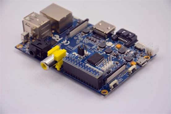
Just insert the module to Banana Pi, like the below picture:
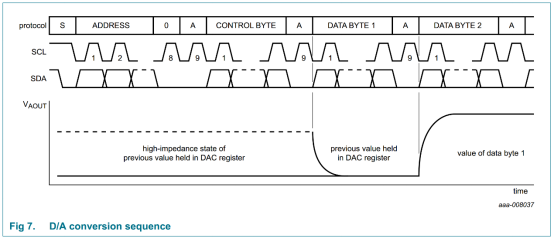
D/A conversion sequence:**
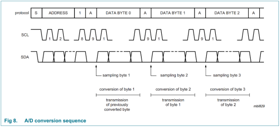
A/D conversion sequence:**
Schematic diagram
How to use
How to use AD/DA module on BPI-M3

Step 1: Download WiringPI
$ git clone https://github.com/BPI-SINOVOIP/BPI-WiringPi.git111 -b BPI_M3
$ cd BPI-WiringPi
$ chmod +x ./build
$ sudo ./build
Step 2:Check the BPI I2C GPIO extend(PCF8591T) device to see if it's on track.(address 0x48)
(I2c port number for M3: 2 )
sudo su
i2cdetect -y 2
. 0 1 2 3 4 5 6 7 8 9 a b c d e f
00: -- -- -- -- -- -- -- -- -- -- -- -- --
10: -- -- -- -- -- -- -- -- -- -- -- -- -- -- -- --
20: -- -- -- -- -- -- -- -- -- -- -- -- -- -- -- --
30: -- -- -- -- -- -- -- -- -- -- -- -- -- -- -- --
40: -- -- -- -- -- -- -- -- 48 -- -- -- -- -- -- --
50: -- -- -- -- -- -- -- -- -- -- -- -- -- -- -- --
60: -- -- -- -- -- -- -- -- -- -- -- -- -- -- -- --
70: -- -- -- -- -- -- -- --```
Step 3:Run the command and see if the LED on the board is working.
low brightness
gpio -x pcf8591:120:0x48 awrite 120 127
hight brightness
gpio -x pcf8591:120:0x48 awrite 120 12
Reference
video demo on youtube:
https://www.youtube.com/watch?v=ltTVOmmqmaE&feature=youtu.be
http://www.nxp.com/products/interface_and_connectivity/i2c/i2c_dacs_and_adcs/PCF8591T.html
